SA1/SA2/SAC1 Wirefree Alarm Systems 1 2 3 4 5 6 7 8 9 0 ON AIR LOW BATT.
FOREWORD The SA1, SA2 and SAC1 Wirefree Alarm Systems comply with the requirements of BS6799 Class 1 for Wireless Alarms. All components are designed and manufactured to provide a high standard of security protection and long, reliable service. In addition, the radio devices are tested and approved by the Radio Regulatory division of the Department of Trade and Industry (DTI) to ensure that they will not interfere with other radio equipment.
CONTENTS Page No. KIT CONTENTS 2 Page No.
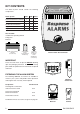
KIT CONTENTS The Alarm System should contain the following components. Alarm System SA1 SA2 SAC1 External Solar Siren Controller 1 1 1 Remote Control 1 1 1 PIR Movement Detectors 2 2 2 Magnetic Contact Set 0 2 2 Keypad 0 1 1 Also included: Installation & Operating Manual Fixing pack Batteries Sealed lead acid battery 6V/1.
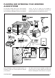
PLANNING AND EXTENDING YOUR WIREFREE ALARM SYSTEM The following example below shows typical property incorporating the suggested positions for the External Siren, Keypad, PIR and Magnetic Detectors for optimum 1 3 2 4 5 6 7 8 9 0 security. Use this as a guide for your installation in conjunction with the recommendations contained in this manual for planning your intruder alarm system. ON AIR LOW BATT.
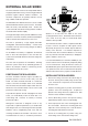
EXTERNAL SOLAR SIREN The Siren and Solar Panel are all encapsulated within a tough polycarbonate housing. This housing provides full protection against adverse weather conditions. All electronic components are specially treated to ensure long, reliable, trouble free operation. An LED Strobe unit is built into the siren to act as a visible deterrent/indication that the system is active. The Strobe LEDs will slowly and alternately flash whether the system is Armed or Disarmed.
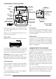
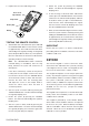
CONFIGURING THE SOLAR SIREN Solar Panel Front cover locating tabs Receiver Aerial Dip switch cover 7.5 Volt DC charging adaptor input Bleep Disable Link Tamper switch Siren Disable Link Jamming Detection Link 6 Volt 1.2Ahr rechargeable battery 9 Volt PP3 initial power up battery Main Configuration Switch (in C.U. Position) C.U. Printed circuit board enclosure C.U.
INITIAL POWER-UP OF THE SOLAR SIREN 1. Connect the 9V PP3 initial power battery to the battery clip. Connect the rechargeable battery to the charging leads. Connect the Red lead to the Red (+ve) terminal and the Black lead the Black (-ve) terminal. Note: Once the batteries have been connected, the unit will be operational and it is important that the solar panel receives sufficient light to maintain the battery charge.
5. Replace the rear cover and fixing screw. House Code Dip Switches Jumper Link Battery Clip Battery TESTING THE REMOTE CONTROL 1. Stand within view of the Solar Siren, press and hold the ‘INSTANT-ARM’ button on the Remote Control for approximately 10 seconds until the Solar Siren acknowledges the signal by emitting one long Beep (unless Beep Disable has been set). This operation takes the Solar Siren out of Service mode and into Operating mode (in a Disarmed state).
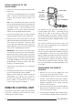
POSITIONING THE KEYPAD The Keypad is suitable for mounting in dry interior locations only. The Keypad should be located within a protected area so that an intruder cannot reach the Keypad without opening a protected door or passing through an area protected by a PIR Movement Detector. The Keypad should be mounted in a position close to the main entrance door so that the user access code can be entered and the alarm system shut down within the 15s entry time period.
does not flash, wait five seconds and re-enter the programming sequence from the beginning. TESTING THE KEYPAD 1. Put the system into Operating mode by pressing and holding the ‘INSTANT-ARM’ button on the Remote Control for approximately 10 seconds until the Siren acknowledges the signal by emitting one long Beep (unless Beep Disable has been set). 2. Arm the system in Instant mode by entering the User Access code followed by the ‘INSTANTARM’ button on the Keypad.
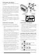
2m - 2.5m Note: DO NOT fix the detector to metalwork or locate the unit within 1m of metalwork (i.e. radiators, water pipes, etc) as this could affect the radio range of the Keypad. 1 2 3 4 5 6 7 8 9 10 Detector Range (metres) 3m INSTALLING THE PIR MOVEMENT DETECTORS Ensure that the system is in service mode. 5m 10m 110° 180° 1. Undo and remove the fixing screw from the bottom edge of the PIR.
To adjust the PCB position simply slide it up and down ensuring that the location legs are aligned with the required position number marked on the board. 7. To refit the PIR detector to the rear cover, offer the detector up to the wall bracket and locate the clips in the top edge into the rear cover. Push the lower edge of the detector into place and refit the fixing screw in the bottom edge of the PIR to secure in position. Do not over-tighten the fixing screws as this may damage the casing.
3. Reconfigure the PIR Detector into Normal operation mode and refit in position. Note: When the detector is fully installed i.e. battery cover is refitted; the unit will not detect movement for approximately 45 seconds after each activation. (This feature is presant to conserve battery power and maximise the battery life). MAGNETIC CONTACT DETECTOR(S) The Magnetic Contact Set comprises two parts; a Detector and a Magnet.
When fixing the Detector with screws the top of the Detector is secured with a keyhole slot over the head of the smaller pan head screw. The bottom of the Detector is secured using the 12mm counter-sunk head screw fitted within the battery compartment. Carefully drill out the centre of the fixing screw hole in the battery compartment using a 3mm drill. Do not over-tighten the fixing screws as this may distort or damage the casing. 4.
TESTING THE SYSTEM INITIAL TESTING As the system is initially installed it is recommended that each device is tested in turn as it is installed, (refer to testing instructions for particular device). TESTING AN INSTALLED SYSTEM 1. Before commencing testing please ensure the following conditions apply: - The system is in Operating mode and Disarmed - There is no movement in any PIR protected area. - All doors/windows protected by Magnetic Contact Detectors are closed.
immediately generate a Full Alarm condition. On returning to and entering the property the system must be Disarmed before opening any protected door or entering an area protected by a PIR movement detector otherwise a Full Alarm condition will occur. Arming The System In Delay Mode The system can be armed in Delay mode using either the Remote Control or the Keypad as follows: Remote Control: Press the ‘DELAY-ARM’ button, Delay mode will arm the system with a 15 second entry/exit delay.
PERSONAL ATTACK (PA) ALARM A full alarm condition can be immediately initiated by the user at any time (whether the system is armed or disarmed) in the event of threat or danger by activating the Personal Attack (PA) facility. To initiate a Personal Attack alarm from the Remote Control slide the Personal Attack switch upwards. To initiate a Personal Attack alarm from the Keypad press and hold both the and buttons 1 2 together for 2 seconds.
BATTERIES battery charge. Failure to maintain charge to the unit will result in the rechargeable battery running unacceptably low. Should this occur, the unit must be recharged from a 7.5Vdc/100mA supply (e.g. from a mains adaptor power supply). When repowering the Solar Siren fit a new 9V PP3 leak proof Alkaline power-up battery to ensure that the Unit receives sufficient power until the solar panel can recharge the main battery. 3.
TROUBLE SHOOTING Symptom / Recommendation Siren gives full alarm condition when arming. 1. Siren anti-tamper switch activated - adjust tamper plunger and ensure that switch fully closes when Siren is mounted. If the wall is excessively uneven, the siren may need relocated to a more suitable position. Siren gives full alarm condition when system has not been activated by an intruder or is disarmed. 1.
TROUBLE SHOOTING - continued Symptom / Recommendation Symptom / Recommendation Magnetic Contact Detector not working. Magnetic Contact Detector false alarming. 1. Ensure batteries are connected with correct polarity. 1. Ensure that gap between magnet and detector is less than 10mm. 2. Ensure battery connections are good. 3. Ensure ‘House Code’ is the same as Solar Siren. 4. Ensure DIP switches 9 and 10 are set correctly. 5. If no external contacts are connected ensure jumper link fitted. 6.
EXTENDING YOUR ALARM SYSTEM Your system may be extended to provide additional protection by adding additional PIR Movement Detectors, Magnetic Contact Sets and Remote Control Units. ACCESSORIES SU1 - ACCESSORY SET Comprises: 2 x Magnetic Contact Sets and 1 x Remote Control Unit. SU1 SU2 - PIR MOVEMENT DETECTORS (TWIN PACK) Comprises: 2 x PIR Movement Detectors. SU2 SU3 - REMOTE CONTROL UNITS (TWIN PACK) Comprises: 2 x Remote Control Units.
If you have a problem with your Alarm, please call the Helpline on: 01268 563273 (Lines open 9.00am to 5.00pm, Monday to Friday). We can solve most problems quickly over the phone. GUARANTEE This product (excluding Alkaline batteries) is guaranteed for one year from the date of purchase against faulty materials or workmanship. We will repair or replace any faulty product.
COMPONENT SPECIFICATION External Solar Siren Novar Electrical Devices and Systems are Quality Assurance Registered to BS EN ISO9001 1994, by Asta. Keypad 1 2 3 4 5 6 7 8 9 0 315 mm 75mm 1 2 ON AIR LOW BATT. 110 30 mm mm ● RF operating frequency: 433MHz ● Range: 50m max. 225 mm 85 mm ● INSTANT-ARM, DELAY-ARM and DISARM buttons ● Personal Attack (PA) switch ● RF operating frequency: 433MHz ● Instant alarm mode ● Sealed lead acid battery 6V/1.