SA3 E PLUS 6 Zone Wirefree Alarm System with Voice Dialler Installation and Operating Instructions
Contents Page No. Kit Contents 3 Introduction and Overview 4 Page No.
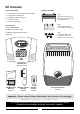
Kit Contents Alarm Components: Batteries included: 1 x 6 Zone LED Control Panel with Voice Dialler x3 2 x PIR Movement Detectors 6V/1.
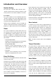
Introduction and Overview System Arming Delay Armed zones will not become fully armed until after the Exit delay period has expired. The system has a ‘Full Arm’ and a ‘Part-Arm’ mode. When a Detector on a Delay Armed zone is triggered, an alarm ‘Full Arm’ will arm all zones while the ‘Part-Arm’ mode condition will not be triggered until after the Entry will only arm the zones that are enabled for ‘Part-Arm’. period has elapsed.
sequence and replay the recorded alarm messages for the set ‘Play Time’. The recipient can acknowledge System House Code In order to prevent any unauthorized attempt to operate or disarm your system, you must set your system to accept radio signals only from your own devices. This is done by setting a series of eight miniature (DIP) switches in all devices (except the Control Panel) to the same ON / OFF combination (the House Code) selected by the user/installer.
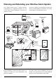
Planning and Extending your Wirefree Alarm System The example below shows a typical property incorporating the suggested positions for the Control Panel, PIR and Magnetic Detectors for optimum security. Use this as a guide for your installation in conjunction with the recommendations contained in this manual for planning your intruder alarm system.
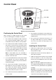
Control Panel Zone LEDs 1 2 3 4 FIRE TAMPER ZONE 5 6 Status LEDs 1 2 3 4 5 6 7 8 9 0 Keypad ESC External view of Control Panel 6. Positioning the Control Panel Control Panel will need connecting to a convenient When choosing a suitable location for the Control telephone point. Panel, the following points should be considered. 1. If the telephone voice dialler is to be used then the 7.
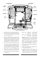
Power Supply Cable Route External Tamper Switch Jumper Link P51 TAMP GND B+ GND N.C. C N.O. GND V+ OUT GND Upper Keyhole Fixing Hole Upper Keyhole Fixing Hole - Terminal (Blue Lead) + Terminal (Blue Lead) + Terminal (Red Lead) - Terminal (Black Lead) Lower Fixing Hole Reset Jumper Link P1 Power Supply Jack Socket Inside view of Control Panel 4. Fit two 18mm No.
Connect the BT plug on the other end of the lead to an appropriate telephone outlet. b) Press If the cable supplied is not long enough to reach a suitable phone point then it will need extending Using a Remote Control Unit: a) With the required House Code already set on the remote control, press the button on the Remote Control. Note: If the Panel Tamper alarm sounds during the installation reset the alarm by pressing: , 3 2 4 The Control Panel will beep twice to acknowledge the signal.
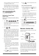
The Remote Control uses a CR2032 type Lithium cell which under normal conditions will have a typical life If movement is detected an alarm signal will be generated, (if the system and alarm zone is armed). in excess of 1 year. Under normal battery conditions the LED on the Remote control will illuminate only Note: ensure that pets are not permitted access to areas fitted with Passive Infra Red Detectors when the when a button is pressed.
When considering and deciding upon the mounting position for the PIR Detector the following points Rear Cover should be considered to ensure trouble free operation: 1. Do not locate the PIR Detector facing a window or where it is exposed to or facing direct sunlight. PIR Detectors are not suitable for use in conservatories. 2. Do not locate the PIR Detector where it is exposed to ventilators. 3. Do not locate the Detector directly above a heat source, (e.g. fire, radiator, boiler, etc). 4.
Note: On initial installation the PIR Detector should be set into Walk Test mode ready for testing. 8. 11. Refit the PIR Detector to the rear cover by offering the PIR Detector up to the rear cover and locate the clips in the top edge into the rear cover.
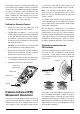
Magnetic Contact Detectors (Ensure back surfaces are flush) Installing and setting the Magnetic Contact Detectors Ensure that the system is in Test mode. 1. 2. Detector Magnet Remove the battery cover by sliding and lifting it off. (DO NOT use a screwdriver to lever off). Alternative Mounting Cut-out for Cable Entry Remove the battery holder by carefully tilting up the end and pulling the connector off the printed circuit board. Battery Cover 5.
8. Slide the two batteries supplied into the battery External Solar Siren holder, ensuring that the positive (+) side is uppermost on each battery as it is installed. 9. The Siren and Solar Panel are all encapsulated within a tough polycarbonate housing. This housing provides full protection against adverse weather conditions. Carefully refit the battery holder onto the Detector ensuring that the spring connectors slide onto either side of the circuit board.
Installing the Solar Siren North Avoid if possible West 1. Remove the fixing screw from the bottom edge of the Solar Siren Siren housing and carefully hinge off the front cover. All electronic components are housed within the front cover. 2. Hold the mounting plate in position and mark the positions of the four mounting holes (a spirit level placed on the casing will ensure a perfect level). Drill four 6mm holes and fit the wall plugs. 3.
Setting the Solar Siren Once you have completed configuring the Solar Siren, refit the DIP switch cover and replace the three cover Ensure that the Solar Siren main configuration switch if fitted on the LED strobe board is set to “SIREN” for use with this alarm system. fixing screws. Do not over tighten the screw as this could damage the thread. Undo the 3 screws holding the DIP Switch cover in place and remove the cover. Initial Power-Up of the Solar Siren 1.
Control Panel cover and tighten the fixing screws on the top edge of the Control Panel. single long beep/LED flash followed immediately by two short beeps/LED flashes to indicate that it has switched into Service Mode. Press Operating Mode: Press and hold the on the Remote Control. Testing the System Initial Testing As the system is initially installed it is recommended that each device is tested in turn as it is installed, (refer to testing instructions for particular device).
Hard-Wired Solar Siren Test Press Factory Defaults 2 User Access Code 1234 Alarm Duration 3 minutes Hardwired Siren Equal to Alarm Duration Zone Operating Mode Zones 1-6: Intruder Part-Arm Zones 1: Disabled Zones 2,3,4,5,6: Active Instant/Delay Zone 1: Delay Zones 2-6: Instant Entry/Exit Delay 30s 5 seconds with the external Solar Siren switching ON and OFF a few seconds after the Control Panel. Entry/Exit Warning Tone On Zone Lockout On Zone LED 3 will be illuminated during the test.
Programming Instructions Press , ? ? ? ? b) Using a Remote Control: , With the required House Code already set in the remote, press the DISARM button on the Remote Control. User Access Code The Arm and Part-Arm LEDs will illuminate and all Zone, Fire and tamper LEDs will flash. The Control Panel will beep twice to acknowledge the signal. The system is now in Programme Mode Note: After programming all required functions press to leave Programme mode and return to Standby.
Press the key corresponding to the required delay setting required, the corresponding zone LED will Part-Arm Default setting: Zone 1 Zones 2-6 illuminate as the setting is changed. to save the new setting and return to Press Press Disabled Active 6 programming mode. Press ESC The zone LEDs corresponding to the zones currently active during Part-Arm mode will be illuminated. LEDs for zones disabled during PART-ARM will be OFF. to return to programming mode without saving.
Entry / Exit Warning Tone Hard-Wired Siren Default setting: ON Default setting: equal to Alarm Duration Press 8 The zone 1 LED will illuminate to indicate the current status of the Entry/Exit warning tone. LED ON LED OFF 1 Press state. ESC 0 The zone LED corresponding to the current setting will illuminate. Tone enabled Tone disabled to change the setting to the opposite Press to save the new setting and return to programming mode. Press saving.
Note: Panic switch, 24 Hour Intruder and Fire modes all operate on a 24 hour basis, (i.e. they are able to to save the new number and return to Press programming mode. initiate a Full Alarm condition at any time irrespective of whether the system is Armed or Disarmed). Press ESC to return to programming mode without saving. Default setting: all zones mode 2 (Intruder).
Replay Alarm Message Call Attempts The recorded alarm message may be replayed and listened to using the telephone handset of a phone connected to another extension socket on the same phone line. This is the total time for which the alarm messages will be played & repeated when a call made by the voice dialer is answered. Press 2 Default setting: 3 3 The zone 1 LED will illuminate. Pick up the telephone handset and press the dialing tone. Press message.
Operating Instructions When leaving the premises, the system should be Armed. However, before doing so, check that all windows are closed and locked, all protected doors are closed and PIR Detectors are not obstructed. Ensure that pets are restricted to areas not protected by PIR Detectors. Arming the System ARM The system can be set in ARM mode using either the Remote Control or the Control Panel as follows: Remote Control: The system has two armed modes, ARM and PARTARM.
Disarming the System Tamper The system can be disarmed using either the Remote Control or the Control Panel as follows: If the battery cover of any device (except a Remote Control) is removed or if the Solar Siren or Control Panel are removed from the wall then a Full Alarm condition will be initiated even if the system is disarmed.
PIR Movement Detector: Batteries Under low battery conditions the LED behind the Detector lens will flash when movement is detected to indicate that the battery needs to be replaced. Before removing the battery cover on any device or opening the Control Panel to replace the battery ensure that the system is put into Test mode to avoid initiating a Full Alarm condition. Under normal battery conditions the LED does not illuminate unless the PIR Detector is in Walk Test mode.
Alarm Record Complete the following information during installation for future reference when adding to your system and to assist Trouble Shooting Zone Settings. Zone Settings Zone Detector(s) Zone Operating Mode Location Instant / Delay Arm Part-Arm 1 2 3 4 5 6 You may make a note of your User Access Code and System House Code below. User Access Code System House Code ECE ON e.g.
Troubleshooting Symptom / Recommendation Symptom / Recommendation Control Unit not working – Power LED OFF Detection Zone triggered (LED flashing) but no alarm is sounding 1. Mains power failure – check if other electrical circuits are operable. 1. Entry/Exit delay still running and not yet expired. 2. Check that the mains adaptor is plugged in and the socket is switched ON. 2. Alarm duration period has already expired and system has reset. 3.
Symptom / Recommendation Symptom / Recommendation Note: If an additional contact is used then the doors / windows protected by both the main wirefree Detector and the additional wired Detector must be closed when either is opened. PIR Movement Detector not detecting a person’s movement 1. Check battery connections are good. 2. Sensitivity detection set too low – reset to high sensitivity detection. If one of the doors/windows is already open then the opening of the other door/window will not be detected.
Extending your Alarm System Your system may be extended to provide additional protection by adding further PIR Movement Detectors, Magnetic Contact Detectors and Remote Control Units.
Notes: 31
Component Specification Control Panel 1 2 3 4 FIRE TAMPER External Solar Siren Magnetic Contact Detector ZONE 5 6 54 185 1 2 3 4 5 6 7 8 mm mm 315 mm 125 9 0 mm ESC 11 14 mm mm 52 230 mm mm ● ● ● ● ● ● ● ● ● ● ● ● ● ● ● ● ● ● ● ● ● RF operating frequency: 433MHz Range: Up to 100 metres Battery Back-up Detector Battery Status Indication 6 Zones Part-Arm Facility Instant or Delayed Alarm Zones Entry/Exit Delay alarm mode Entry/Exit Delay Warning (selectable) 90dB High Pow