SA5 E 36 Zone Wirefree Alarm System with Voice Dialler POWER ALARM STATUS 1 2 3 4 5 6 8 9 7 0 ALARM MEMORY / TEL MESSAGE LINE STATUS ESC Installation and Operating Instructions
Contents Page No. Page No.
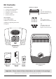
Kit Contents Alarm Components: Batteries included: 1 x 36 Zone LCD Control Panel x3 2 x PIR Movement Detector 6V/1.
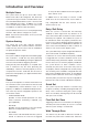
Introduction and Overview Multiple Users an entry will be recorded in the Event Log but an alarm will not occur. The system allows for up to 6 User Codes and a Master User Code to be configured. This allows the system Event Log to maintain a record of which users have armed and disarmed the system. Each user will have a different User Code. In addition a 4 second voice recorder facility enables the users name to be recorded for use with the Latch-Key facility.
system is armed and a zone configured as a ‘Master Voice Dialler Walk Through’ zone is triggered, the zones Entry- If the Voice Dialler is enabled and an alarm condition Delay will start. Any zones configured as ‘Slave Walk occurs, the system will call for help using your recorded Through’ will be disabled to allow free access to the alarm messages and up to four telephone numbers. Control Panel to disarm the system before the EntryDelay expires an alarm occurs.
Voice Memo interference operating legally or illegally on the same frequency. In addition it is also possible to record messages at If you are planning to operate the Jamming Detection feature we recommend that you the Control Panel using the ‘Voice-Memo’ facility. wait at least 30 days before activating this feature, Each voice-memo message is limited to a maximum this will allow time for you to become familiar with the duration of 30 seconds and counts as an answer operation of your system.
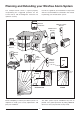
Planning and Extending your Wirefree Alarm System The example below shows a typical property incorporating the suggested positions for the Control Panel, PIR and Magnetic Detectors for optimum security. Use this as a guide for your installation in conjunction with the recommendations contained in this manual for planning your intruder alarm system.
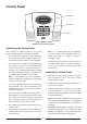
Control Panel LCD Window Status LEDs POWER ALARM MEMORY / TEL MESSAGE ALARM STATUS 1 2 3 4 5 6 8 9 7 LINE STATUS Keypad 0 ESC External view of Control Panel Positioning the Control Panel When choosing a suitable location for the Control Panel, the following points should be considered. 1. 2. Note: It is recommended that the telephone connection lead is not extended beyond 5m before connecting to a telephone master or secondary outlet.
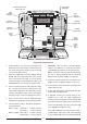
Power Supply Cable Route External Tamper Switch Jumper Link P51 TAMP GND B+ GND T1 T2 GND T3 T4 N.C. C N.O. GND V+ Upper Keyhole Fixing Hole OUT GND Upper Keyhole Fixing Hole - Terminal (Blue Lead) + Terminal (Blue Lead) + Terminal (Red Lead) - Terminal (Black Lead) Lower Fixing Hole Reset Jumper Link P1 Power Supply Jack Socket Inside view of Control Panel 4. 5. 6. Fit two 18mm No.
Note: If the Panel Tamper alarm sounds during the Press the other buttons on the Remote Control in installation reset the alarm by pressing: turn, as each button is pressed the Control Panel , 1 3 2 will beep and show the button being pressed on 4 , the display. on the Control Panel Keypad. 4.
The PIR Detector is powered by a PP3 Alkaline Setting the Remote Control battery which under normal conditions will have an 1. Remove the front cover by undoing the small expected life in excess of 1 year. When the battery screw on the rear of the Remote Control. 2. level drops, with the PIR Detector in normal operation Located above the battery is a row of 8 DIP mode and the battery cover fitted, the LED behind switches. Select and record a random combination the detection window will flash.
4. Where possible, mount the PIR Detector in the corner of the room so that the logical path of an intruder would cut across the fan detection pattern. PIR Detectors respond more effectively to movement across the device than to movement directly towards it. 5. Do not locate the PIR Detector in a position where it is subject to excessive vibration. 6. Ensure that the position selected for the PIR Detector is within effective range of the Control Panel.
DIP4 of SW3 is used to set the PIR Detector for approximately 2-3 minutes until the PIR Detector walk test mode, which allows the operation of the has warmed up and stabilized. The LED will then Detector to be checked during installation without stop flashing and turn OFF. triggering a Full Alarm. 10. Check that the PIR Detector PCB is located and set Walk Test mode Normal operation down ensuring that the location legs are aligned with the required position number marked on the board.
If necessary adjust the detection range by Slide Open and Lift Off Do Not Use A Screwdriver changing the mounting position of the PCB within the PIR housing. Note: In normal operation, the LED behind the PIR lens will not flash on movement detection, Raised Head Screw Key-hole Slot Fixing (underside) (unless the battery is low).
6. 2. Remove the battery cover by sliding off.. Set the House Code for the Magnetic Contact Detector by setting DIP switches 1-8 to the same As the battery cover is removed the LED on the ON / OFF combination as the House Code DIP Detector will illuminate for approx. 1 second to switches in all other system devices. indicate that the tamper switch has been Terminal Block for Additional Wired Magnetic Contact Detector T1 Anti-Tamper Switch SW2 Jumper Link S2 activated.
During Ensure that the position selected for the Solar Siren darkness, only a small amount of energy is required to is within effective range of the Control Panel, (refer to operate the Solar Siren unit. “Testing the Control Panel & Remote Control”). charges the battery during daylight hours. An Alkaline 9V PP3 battery is supplied in the Solar Siren to boost the initial power to the unit when the Installing the Solar Siren system is first activated until the Solar Panel charges 1.
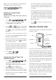
Solar Panel Front Cover Locating Tabs Receiver Aerial Tamper Switch 7.5 Volt DC Charging Adaptor Input DIP Switch Cover Beep Disable Link P2 P3 6 Volt 1.2Ahr Rechargeable Battery Siren Disable Link P1 Jamming Detection Link 1 2 3 4 5 6 7 8 9 ON 9 Volt PP3 Initial Power-Up Battery House Code DIP Switches 1-8 Alarm Duration DIP Switch 9 C.U. SIREN Main Configuration Switch (in SIREN Position) C.U.
2. 3. Press the anti-tamper switch, the LEDs will flash The Control Unit incorporates a terminal block for together to indicate that the unit is operational. connection of hard-wired Zones (7-10), Siren or Telephone Dialler unit. The connection terminal block is Hinge the front cover locating tabs over the top located inside the Control Panel behind the front cover. edge of the back plate and carefully push the base of the siren cover into place.
Use the and menu and press Select ‘Relay Test’ to operate the External hardwired buttons to scroll through the to select the displayed test (N.O./N.C.) Relay contacts. function or sub-menu. Press Note: After completing all required test functions press ESC ESC to exit Alarm Test and return to the top level Test Mode menu. to leave Test mode and return to Standby.
Factory Default Settings User Setup Full Arm Setup Users 1- 6 Not programmed Exit Delay ON, 30 seconds Master Password 1234 Entry Delay Beep ON Exit Delay Beep ON System Setup Part-Arm 1 Setup House Code Not programmed Alarm Time ON, 180 seconds Wirefree Siren ON RF Jamming Detection OFF Back Light 10 seconds Part-Arm 2 Setup Alarm Relay On Until Disarm Exit Delay ON, 30 seconds Zone Lockout ON Entry Delay Beep ON Remote Phone Control ON Exit Delay Beep ON Rings to Answe
Reset Factory Default Conditions 1. Press , ? ? ? ? , User Access Code to place the system in Test Mode. 2. Undo the Control Panel cover fixing screws and open the cover. 3. Switch OFF the mains supply to the plug-in PSU Adapter and remove the plug from the DC power socket in the Control Panel.. 4. Remove either back-up battery and disconnect the battery leads. 5. Set jumper link P1 to the ON position. Jumper Link P1 OFF 6.
Programming Instructions Press , ? ? ? ? Enter the new 4 digit Access Code and then , Master User Access Code Press The Arm and Part-Arm LEDs will illuminate and all Press Zone, Fire and tamper LEDs will flash. and message for use with the Latch Key facility. to select the e.g. “system disarmed by User-1”. displayed programming function or sub-menu. Scroll through the menu until ‘:2 Record User Note: After programming all required functions press ESC to exit without saving.
System Setup PROGRAM MODE CODE: 2. SYSTEM SETUP 2-1 Learn House Code 2-3 Wirefree Siren: xxx Press DISARM on Remote...
Wirefree Solar Siren Default setting: ON Until Disarm Default setting: ON Scroll through the menu until ‘2-6 Alarm Relay’ is Scroll through the menu until ‘2-3 Wirefree Siren’ is displayed. The current setting will also be displayed. displayed. The current setting will also be displayed. To change the setting press To change the setting press . . Scroll through available options, (2s, 30s, 60s, Press 1 to enable the Solar Siren, or Press 3 to disable the Solar Siren.
To change the setting press . To change the setting press . Enter the required number of rings (1-30) before Scroll through available options, (Voice Dialler and the Control panel will pick up the call Remote Manager) until the required setting is displayed. Press to save and exit, or Press Press ESC Press Call Abort This feature, if enabled, will delay the activation of the telephone dialler following an alarm for a period of approx 10s to allow the system to be disarmed.
Zone Setup PROGRAM MODE Code: 3.
Test Entry Delay - when the system is armed, any detector on the zone Scroll through the menu until ‘3-5 ENTRY DELAY’ is will generate an entry in the Event-Log without displayed. The current settings will also be displayed. initiating an alarm condition. To change the settings press Note: . Personal Attack, 24-hour Intruder and Fire modes all operate on a 24 hour basis, (i.e.
Part-Arm 2 Walk Through This controls whether the zone is active when Part- Default setting: OFF Arm 2 is armed. Scroll through the menu until ‘3-8 Z01 Walk Through’ Default setting: OFF is displayed. The current setting will also be displayed. Scroll through the menu until ‘3-7 Z01 Part-Arm 2’ is To change the setting press . displayed. The current setting will also be displayed. Scroll through available options, (Off, Master and To change the setting press Press 1 Press 3 .
Note: After recording the message, press Notes: Press ESC to stop the recorder and cancel any remaining to insert a 3.5 second pause in the message time. dialing sequence. Press to move the cursor left. Press to move the cursor right. Press to delete the character under the Press to return to the top level Voice Dialler ESC setup menu. Replay Alarm Messages cursor.
Tel Confirm Times Note: After configuring Full Arm press ESC to return to the top level programming menu. This sets the number of acknowledged phone numbers required to stop the voice dialler. For example if set to "2" then the dialing sequence will continue until an Exit Delay acknowledgment is received from two different Scroll through the menu until ‘5-1 EXIT-DELAY’ is numbers, (e.g. Phone No.1 and Phone No.3). displayed. The current settings will also be displayed.
Exit Delay Beep Delay Period This controls the warning beep which operates during Default setting: 30 seconds the Exit Delay period when Full Arm is initiated. Scroll through the menu until ‘6-1-2 Delay Time’ is Default Setting: ON displayed. The current settings will also be displayed. Scroll through the menu until ‘5-3 Exit Delay Beep’ is To change the settings press . displayed. The current setting will also be displayed. Enter the required delay period (10 to 250s).
Part-Arm 2 Setup Entry Delay Beep This controls the warning beep which operates during PROGRAM MODE Code: the Entry Delay period when Part-Arm 2 is active. Default Setting: ON 7. PART ARM 2 SETUP Scroll through the menu until ‘7-2 Entry Delay Beep’ is 7-1 EXIT Delay xxx xxxs Select OFF->3 ON->1 7-1-1 Status xxx displayed. The current setting will also be displayed.
Time Press Scroll through the menu until ‘8-2 Time’ is displayed. Press ESC to save and exit, or to exit without saving. The current setting will also be displayed. To change the setting press Selected-Users Setup . This allows controls over which users the Latch Key Enter the time in the format ‘hh:mm:ss’. Press facility operates with when set to ‘Selected-Users’. to save and exit, or Press ESC Default setting: OFF to exit without saving.
Home Automation Setup Remote Manager Setup This feature is not available for use in the UK. PROGRAM MODE Code: Answer Phone Setup 12. REMOTE MANAGER SETUP PROGRAM MODE Code: 11. ANSWER PHONE SETUP 11-1 Status xxx Select ON->1 OFF->3 Start... YES->1 NO->3 12-2 Unit ID No: xxxxxxxxxxxxxxxx Enter Phone No: Enter Unit ID: Scroll through the menu until ‘12. REMOTE 11-3 Replay Greeting 11-2 Record Greeting 12-1 Phone No: xxxxxxxxxxxxxxxx MANAGER SETUP’ is displayed and press . Playing...
Operating Instructions Arming the System When leaving the premises, the system should be Armed. However, before doing so, check that all windows are closed and locked, all protected doors ARM are closed and PIR Detectors are not obstructed. The system can be set in ARM mode using either the Ensure that pets are restricted to areas not Remote Control or the Control Panel as follows: protected by PIR Detectors.
Disarming the System Personal Attack (PA) Alarm The system can be disarmed using either the Remote A full Alarm condition can be immediately initiated at Control or the Control Panel as follows: any time (whether the system is Armed or Disarmed) in the event of threat or danger by activating a Panic Remote Control: Button on either the Remote Control or the Control Press the Panel. button.
If when the system is disarmed the ‘ALARM MEM’ LED At the end of each message there will the option of is flashing and the panel beeps every 10 seconds, this deleting the message just heard. indicates that an alarm has occurred. To cancel the LED To delete the message and stop the beeping you must access the event log. To access the Event Log, (with the system in Standby): Press 1 to delete the message Press 8 Press 1 to re-confirm and actually delete the . message.
1. Dial up the system and hang up after two Battery Monitoring rings. All system devices continuously monitor their battery condition. The Control Panel also monitors the battery 2. Redial up the system within 30s, the system condition of all PIR and Magnetic Detectors. If the will pickup the phone after 1 ring. battery level of any device drops below acceptable 3. Enter the User Access code as normal. levels then its low battery indication will be activated.
Maintenance Your Alarm System requires very little maintenance. However, a few simple tasks will ensure its continued reliability and operation. system to a new premises) first put the system into Test mode before removing the Control Panel cover and disconnecting the power supply and backup batteries. To power-down the Solar Siren undo the fixing screw on the bottom edge and remove the front cover.
Alarm Record Complete the following information during installation for future reference when adding to your system and to assist Trouble Shooting Zone Settings. Zone Settings Detector Type(s) Zone Location Type Final Exit / Walk Through Entry Delay Chime Part-Arm Part-Arm 2 1 Arm 1 2 3 4 5 6 7 8 9 10 You may make a note of your User Access Codes and Installer Access Code below.
Troubleshooting Symptom / Recommendation Symptom / Recommendation Control Unit not working – Power LED OFF or flashing Cannot record Voice-Memo message at Control Panel. 1. Mains power failure - check if other electrical circuits are operable. 1. No space in message store, 6 messages already recorded. 2. Check that mains adaptor is plugged in and socket is switched ON. Control Unit Not Contacting Remote Manager Service on Alarm 3. Check mains fuse in Plug has not blown. 4.
Symptom / Recommendation Symptom / Recommendation Siren not responding to Control Panel PIR Movement Detector not detecting a person’s movement 1. Ensure that the ‘House Code’ is correctly set. 1. Check battery connections are good. 2. Ensure main Siren configuration switch is set to SIREN. 2. Pulse count set too high - reset to one pulse detection. 3. Incorrect User Access code being entered at Control Panel. 3. Check that the detector is correctly set up.
Extending your Alarm System Your system may be extended to provide additional protection by adding further PIR Movement Detectors, Magnetic Contact Detectors and Remote Control Units.
Component Specification Control Panel POWER ALARM STATUS 1 2 3 4 5 6 8 9 7 ALARM MEMORY / TEL MESSAGE 0 External Solar Siren 54 185 LINE STATUS Magnetic Contact Detector mm mm 315 mm 125 mm ESC 11 14 mm mm 52 230 mm mm ● ● ● ● ● ● ● ● ● ● ● ● ● ● ● ● ● ● ● ● ● RF operating frequency: 433MHz Range: 50m max. RF Jamming Detection 6 Users + Master User 6 Wirefree Zones + 4 Wired zones Independently programmable Entry and Exit delays.