SA5 6 Zone Communicating Wirefree Alarm System 1 2 3 4 5 6 7 8 9 * 0 # ESC ENTER Installation & Operating Manual
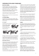
FOREWORD All devices in this wirefree Alarm System are designed and manufactured to provide a high standard of security protection and long, reliable service. Note: The effect on the range of multiple walls is cumulative. e.g. if there are two brick walls in the way, the range will be reduced by up to 40% by each wall. The system is designed for ease of installation using only conventional domestic tools.
CONTENTS EXTERNAL SOLAR SIREN 18 General Information 18 Positioning the Solar Siren 18 KIT CONTENTS 4 INTRODUCTION AND OVERVIEW 5 Installing and Configuring the Solar Siren 19 Multiple Users 5 Power-up the Solar Siren 20 System Arming 5 Entry/Exit Delay 5 EXTERNAL CONNECTIONS 21 Zones 5 TESTING THE SYSTEM 21 Zone Lockout 6 FACTORY SETTINGS 23 Quick Set 6 Reset Factory Settings 24 Final Exit Set Zone 6 Walk Through Zone 6 PROGRAMMING 24 Omit Zone 6 User Setup 25 E
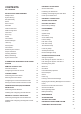
KIT CONTENTS The Alarm System should contain the following devices: 1 x Solar Siren 1 x Control Panel 1 x Remote Control 2 x PIR Movement Detectors 2 x Magnetic Contact Detectors Also included: Telephone Connection Lead Power Supply Adaptor Installation & Operating Manual Fixing pack Batteries PIR Movement Detector Magnetic Contact Detector � � � � � � � � � � � � ��� ����� Control Panel Solar Siren WP1.2-6 6V/1.2Ahr Sealed lead acid battery (supplied fitted in Siren) WP1.2-6 WP1.
INTRODUCTION AND OVERVIEW MULTIPLE USERS The system allows for up to 6 Users and a Master User to be configured. This allows the system Event Log to maintain a record of which users have armed and disarmed the system. Each user will have a different User Access Code. In addition a 4 second voice recorder facility enables the user’s name to be recorded for use with the Latch Key facility. Only the Master User has access to the programming functions and is able to configure the system.
3 times then that zone will be ‘Locked Out’ and any further alarm signals from that zone will be ignored until the system is disarmed. Note: The ‘Zone Lockout’ feature can be disabled if required. QUICK SET The system may be fully armed in 5 seconds using the quick set facility, overriding the programmed exit-delay. This is useful for setting the system at night when the Exit-Delay warning beep will be silenced after just a few seconds. FINAL EXIT SET ZONE Triggering a detector on a Final Exit zone (e.g.
sequence is cancelled/acknowledged by the recipient. For example, the Latch Key facility is useful to inform parents that a child has returned from school and Disarmed the system. ANSWERPHONE The Control Panel includes an answerphone facility. The answerphone will record and store a maximum of 6 messages with each message being limited to 30 seconds duration. Messages may be retrieved either direct from the Control Panel or by dialling into the system from a phone.
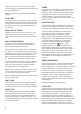
PLANNING AND EXTENDING YOUR ALARM SYSTEM Before attempting to install your Alarm System it is TYPICAL INSTALLATION important to study your security requirements and plan The following example below shows typical property your installation. incorporating the suggested positions for the Siren, PIR PIR Movement Detectors are used to protect the main and Magnetic Contact Detectors. Use this as a guide areas of the property, (e.g.
Typical Installation using only detectors supplied: 1. Place the 1 Magnetic Contact Detector (configured st on zone 1) on the front door. 2. Place the 1st PIR Detector (also configured on zone 1) in the hall covering the Control Panel and routes between downstairs rooms. 3. Place the 2nd Magnetic Contact Detector (configured on zone 2) on the back door or patio doors. 4.
Any number of Remote Control Units can be used with your system, providing they are all coded with the same system House Code. Testing the Remote Control: 6. Press the button. The Transmit LED should illuminate while the button is pressed and extinguish within 1 second of releasing the button The Remote Control is powered by a CR2032 type Lithium cell which under normal conditions will have an expected life of approximately 1 year. Under normal 7.
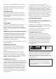
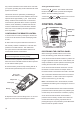
���� ��� �� ��� �� �� ��� �� �� ���� � ���� ��� �� ��� ��� ��������������� ������������� �������� ������������ ����������� ������������� ����������� ������������� ����������� ���������� ������������ ���������� ���������� ���������� ����������� ���������� ����������� ������������ ���� ������������ ������� ������������ ����������� Inside View of Control Panel 5. The Control Panel must be located within reach Note: The wall plugs supplied with the product are not of a mains socket.
7. Ensure that the “Reset” and the “Hard-Wired Siren Note: If the Control Panel Tamper alarm sounds during tamper detect” jumper links are set in the OFF position. the installation reset the alarm by pressing , ������ ���� ������ ���� , User Access Code �� ��� on the Control Panel. �� ��� ��� IMPORTANT! The keys must be pressed firmly and within 3 seconds of each other. If you make a mistake, press and start the sequence again.
5. Press 6. Press To conserve power and maximise battery life the PIR to save the new setting. , Detector will only detect movement if there has been to return to Standby. no movement detected within the previous 2 minutes, TESTING THE CONTROL PANEL & REMOTE CONTROL 1. Press , , User Access Code to put the system into Test mode. ‘TEST MODE – WALK TEST’ will be displayed. 2. Press to activate Walk Test. (this is known as the detectors “sleep period”).
When deciding upon the mounting position for the 2. Carefully drill out the required mounting holes in the detector the following points should be considered to rear cover using a 3mm drill according to whether the ensure trouble free operation: unit is being mounted in a corner or against a flat wall. 1. Do not position the detector facing a window or 3. Using the rear cover as a template, mark the where it is exposed to or facing direct sunlight. PIR positions of the fixing holes on the wall.
8. To select the required sensitivity, set DIP switch 5 of Testing the PIR Detector: SW3 as follows: 12. Ensure that the LED indicator has stopped flashing rapidly. ON = HIGH sensitivity OFF = LOW sensitivity 13. Use the and buttons to scroll through the menu until ‘WALK TEST’ is displayed and press ON . 1 2 3 4 5 ‘Walk Test Waiting…’ will be displayed. Note: The recommended setting is HIGH.
MAGNETIC CONTACT DETECTORS The Magnetic Contact Set comprises 2 parts; Detector and Magnet. They are designed to be fitted to either doors or windows with the Magnet mounted on the opening part of the door/window and the Detector mounted to the frame. Do not fix the Detector onto or very close to metalwork (i.e. radiators, water pipes, etc.) as this could affect the radio range of the device.
3. If fixing the detector with screws, first remove the 6. Configure the alarm zone which the detector will battery holder by carefully tilting up the end and pulling operate on with DIP switches 9-11 as follows: away from the printed circuit board (PCB). The top of the Detector is secured by hanging the keyhole slot over the head of the 10mm pan head screw. The bottom of the Detector is secured using the 12mm counter-sunk head screw fitted within the battery compartment.
Tamper’ will be displayed. POSITIONING THE SOLAR SIREN 12. Open the door/window to remove the Magnet from The Siren should be located as high as possible in a the Detector. prominent position on an external wall so that it can be As the Magnet is moved away from the Detector the on a sound flat surface so that the rear tamper switch is LED indicator will illuminate for approximately 1 second to show that the Detector has been triggered and a signal is being transmitted.
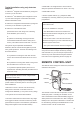
�������������� ����������� ����������� ����������������� ����� ���������� ����� ������ ������ ������������������ �� ���� ������������ ������� ������� �������������� ������������������������������������������������� �� ���������� ���������������� ���������������� ������������������������� ������������������� ���� ����������������� �� �� ���� ����� �������������� ������������ ����������������� ����� INSTALLING AND CONFIGURING THE SOLAR SIREN 8.
12. If for any reason you need to disable the Siren, remove jumper link P3 on the circuit board. This will prevent the Siren from sounding during an alarm condition. However, the Siren will still beep Testing the Solar Siren: 4. Use the and buttons to scroll through the menu until ‘ALARM TEST’ is displayed and press to acknowledge signals from the Remote Control, . (provided the beep feature has not been disabled). 5.
TESTING THE SYSTEM The Control Unit incorporates a terminal block for connection of hard-wired zones (7-10) and a wired Siren unit. The connection terminal block is located The Control Panel has a built in test facility to enable inside the Control Panel behind the front cover. To you to test the system at any time. However it is access the terminal block you must first put the system recommended that the system is tested at regular into Test Mode to prevent an alarm occurring.
FACTORY SETTINGS VOICE DIALLER TEST 1. Scroll through the top level Test Mode menu until ‘VOICE DIALER TEST’ is displayed and press . 2. If the Voice Dialler is enabled it will be activated and will follow the normal calling process. It will call set number of times with the main and Intruder alarm messages will be replayed to the called number. The test sequence may be cancelled either at the pressing the 3. Press or by the call recipient button on their telephone keypad.
RESET FACTORY SETTINGS 1. Press , , . User Access Code PROGRAMMING INSTRUCTIONS With the system in Standby (i.e. with the display This puts the system into Test Mode. showing “DISARM READY”). 2. Undo the Control Panel cover fixing screws and Press , open the cover. 3. Remove the DC power jack, then remove and disconnect one of the back-up batteries. 4. Set jumper link P1 to the ON position.
STANDBY MODE PROGRAM MODE Code: Master User Access Code 7. PART ARM SETUP 8. TIME & DATE SETUP 9. LATCHKEY SETUP 8-1 Date DD/MM/YY 000 8-2 Time HH/MM/SS Save & exit Exit without saving HH/MM/SS Enter new system line USER SETUP Telephone Application Setup. If using any of the telephone based functions, (e.g. PROGRAM MODE Code: Answerphone, Voice Dialler, Remote Phone Access & Control etc) the Dial Method must be set according to the exchange type, (i.e. Pulse or Tone/DTMF).
USERS 1-6 To change the setting press Default setting: not programmed Scroll through the menu until the required User ‘USER _ SETUP’ is displayed and press . User Access Code Scroll through the menu until ‘:1 Access Code’ (and the current setting) is displayed. To change the setting press . Enter the new 4 digit Access Code and then Press to save and exit, or Press to exit without saving.
SYSTEM SETUP ������� ���� ����� �� ������ ����� ��� ����� ����� ���� ��� �������� ������ ��� ����� ������ �� ��������� ��� ���� ����� ��� ������ ����� ������ ��� ���� ������� ��� ��� ����� �� ������ ������ �� ����� ����� ������ ����� ������ ��� ��� ��� ��� ���� ���� ������ ��������� ��������� ����� � ���� � ���� ���� ����� � � �� � � � ���� � ���� ���� ����� � � �� � � ��� ����� ���� ��� � ���� ��� �� ������� ���������� ��� ��� ����� ����� �������������� ������ ����� ������ ����� ������ ���
Scroll through the menu until ‘2-2-1 Status’ (and the current setting) is displayed. To change the setting press Detection’ (and the current setting) is displayed. To change the setting press . Press to enable the Siren, or Press to disable the Siren. . Press to enable Jamming Detection, or Press to disable Jamming Detection. CONTROL PANEL BACK LIGHT Siren Duration This controls how long the display backlight will remain Default setting: 180 seconds illuminated for after a key is pressed.
REMOTE PHONE ACCESS AND CONTROL Scroll through the menu until ‘2-11 Dial Method’ (and If enabled, this allows the system to be remotely the current setting) is displayed. controlled via the telephone. To change the setting press . Default setting: OFF Scroll through the menu options, until the required Scroll through the menu until ‘2-8 Remote Phone setting is displayed. Control’ (and the current setting) is displayed.
ZONE SETUP The parameters in this menu allow each zones specific function to be configured.
24 Hour Intruder - used to provide 24 hour monitoring CHIME of areas requiring continuous security protection even This controls whether the zone will operate with Chime while the system is Disarmed, (e.g. gun lockers). Activation of any detector on a security zone will Mode. immediately initiate an Alarm. Default setting: OFF Fire - use to provide 24 hour monitoring of any Fire/ Scroll through the menu until ‘3-4 Z01 Chime’ (and the Smoke detectors fitted to the system.
PART-ARM 1 This controls whether the zone is active when Part-Arm 1 is armed. Default setting: zones 1-4: Zones 5-10: ON OFF Scroll through the menu until ‘3-6 Z01 Part-Arm 1’ (and the current setting) is displayed. To change the setting press . Press to enable the zone in Part-Arm 1, or Press to disable the zone in Part-Arm 1. PART-ARM 2 This controls whether the zone is active when Part-Arm 2 is armed.
VOICE DIALLER SETUP The parameters in this menu allow the setting of the systems Voice Dialler. It allows up to 4 phone numbers to be entered and the call routing sequence to be set by defining which number is called and the number of attempts made to contact each number. The alarm voice messages are also recorded here. Note: For the Voice Dialler to operate correctly the “Dial Method” and “Dialler Mode” (see system setup) must be correctly set and programmed. PROGRAM MODE Code: 4.
ALARM MESSAGE PLAY TIME CALL ROUTING This is the total time for which the alarm messages will This controls which phone numbers in the dialling be played & repeated by the Voice Dialler. sequence are enabled and will be called when the Voice Dialler is activated. Default setting: 70 seconds Scroll through the menu until ‘4-2 Message Play Time’ Scroll through the menu until ‘4-5 CALL ROUTING’ (and the current setting) is displayed. To change the settings press (and the current setting) is displayed.
CALL ATTEMPTS Scroll through the menu until ‘5-1-1 Status’ (and This sets the maximum number of times that the dialler the current setting) is displayed. will attempt to contact each enabled telephone number in the call routing sequence. Default setting: 3 Scroll through the menu until ‘4-7 Call Attempts’ (and the current setting) is displayed. To change the setting press To change the setting press . Press to enable the Exit-Delay, or Press to disable the Exit-Delay.
PART-ARM 1 SETUP Press to save and exit, or The parameters in this menu control the systems Exit- Press to exit without saving. Delay period and the Entry/Exit Delay warning beeps Press during Part-Arm 1 mode. to return to top level Part Arm 1 Setup menu. PROGRAM MODE Code: ENTRY-DELAY BEEPS Allows the Entry-Delay warning beeps when activating 6. PART ARM 1 SETUP Part-Arm 1 to be switched ON or OFF.
PART-ARM 2 SETUP The parameters in this menu control the systems ExitDelay period and the Entry/Exit Delay warning beeps Press to save and exit, or Press to exit without saving. Press during Part-Arm 2 mode. to return to top level Part Arm 2 Setup menu. PROGRAM MODE Code: ENTRY-DELAY BEEPS Allows the Entry-Delay warning beeps when activating 7. PART ARM 2 SETUP Part-Arm 2 to be switched ON or OFF.
TIME & DATE SETUP LATCH KEY SETUP The parameters in this menu allow the systems The parameters in this menu configures which users clock and calendar (required for the Event Log) to be the Latch Key feature operates with and the telephone configured. numbers that the system dials when the Latch Key is Note: The clock will require updating to reflect any time changes due spring/autumn daylight saving. activated.
SELECTED-USERS SETUP ANSWERPHONE SETUP This configures the individual users that the Latch Key The parameters in this menu allow the systems operates with when set to ‘Selected-Users’. answerphone facility to be configured and the greeting message to be recorded. Default setting: OFF Scroll through the menu until ‘9-2 SELECTED USER SETUP’ is displayed and press .
REPLAY ANSWERPHONE GREETING Scroll through the menu until ‘10-3 Replay Greeting’ is displayed. To replay the recorded greeting message press . REMOTE MANAGER SETUP The parameters in this menu configure the system telephone dialler to interface to the Alarm Monitoring Press to save and exit, or Press to exit without saving. UNIT ID Scroll through the menu until ‘11-2 Unit ID No:’ (and the current setting) is displayed. To change the setting press .
OPERATING INSTRUCTIONS When leaving the premises, the system must be Armed. However, before doing so, check that all windows are closed and locked, all protected doors are closed and PIR Detectors are not obstructed. Ensure that pets are restricted to areas not protected by PIR Detectors. The system has 3 arming modes, ARM, Part-Arm 1 and Part-Arm 2.
If when the system is disarmed the ‘ALARM MEM’ LED is flashing and the panel beeps every 10 seconds, this indicates that an alarm has occurred. PERSONAL ATTACK (PA) ALARM An alarm can be immediately triggered at any time (whether the system is Armed or Disarmed) in the To stop the LED flashing and panel beeping either event of threat or danger by activating a Personal a. Press Control Panel as follows: . or b. Inspect the Event Log to find out the cause of the alarm a.
Press to access the Event Log, (from Standby Mode only). The Event Log will automatically display each event in turn starting with the most recent. The data for each event is shown on 2 screens with each screen being displayed for 5 seconds. Use and to delete the message Press to re-confirm deletion of the message. Note: Press at either stage to cancel delete and move on to the next message. After all messages have been replayed the system will to manually scroll through the events.
Press to switch the Siren between Service Mode and Operating Mode. LED 5 will illuminate to show that the appropriate signal is being transmitted. After approximately 6 seconds the Siren will produce a single long beep to indicate that it has switched into Operating Mode in a Disarmed state. Press to return to Standby mode. BATTERY MONITORING All system devices continuously monitor their battery condition.
MAINTENANCE Your Alarm System requires very little maintenance. However, a few simple tasks will ensure its continued reliability and operation. IMPORTANT: If, for any reason you have to completely power-down the system (e.g. to move the system to new premises), first put the system into Service Mode before removing the Siren cover and disconnecting the main rechargeable and initial power-up batteries.
ALARM RECORD Complete the following information during installation for future reference, when adding to your system and to assist trouble shooting. Zone Settings Zone Detector Type(s) Location FinalExit / WalkThrough settings Type Entry Delay Chime Arm PartArm 1 PartArm 2 1 2 3 4 5 6 7 8 9 10 You may make a note of your User Access Codes and Installer Access Code below. User Access Codes User 1: User 2: User 3: User 4: User 5: User 6: Master User: e.g.
TROUBLE SHOOTING Symptom / Recommendation Control Unit not working – Power LED OFF or flashing. 1. Mains power failure - check if other electrical circuits are operable. Siren not responding to Control Panel. 1. Ensure ‘House Code’ is correctly set to the same code as all other system devices. 2. Ensure main Siren configuration switch is set to SIREN. 2. Check that mains adaptor is plugged in and socket is switched ON. 3. Incorrect User Access code being entered at Control Panel. 3.
5. Ensure that detector is mounted the correct way up, (i.e. with detection window at the bottom). 6. Ensure that the detector is mounted at the correct height, (i.e. 2-2.5 metres). 7. Allow up to 3 minutes for detector to stabilize and become fully operational. Leave the area for this period. 8. Ensure detector is within effective radio range of the Control Panel and is not mounted close to metal objects which may interfere with Radio transmission.
EXTENDING YOUR ALARM SYSTEM The following additional accessories are available to enhance your system and provide further protection and a higher level of security where required. ACCESSORIES SU1 ACCESSORY SET SU2 PIR MOVEMENT DETECTORS SU3 REMOTE CONTROL UNITS 2 x Magnetic Contact Detectors and 1 x Remote Control Unit. 2 x PIR Movement Detectors. 2 x Remote Control Units.
COMPONENT SPECIFICATION External Solar Siren Control Panel Magnetic Contact Detector 52 mm 225 85 mm mm • RF operating frequency: 433MHz • Sealed lead acid battery 6V/1.2Ahr • Solar Panel 7.