Wireless Security Alarm SL1/SL2 0 1 2 3 4 5 6 1 7 8 9 2 Installation & Operating Manual
FOREWORD All devices in this Wireless Alarm System are designed and manufactured to provide long reliable service. The system is designed for ease of installation using only conventional domestic tools. However, it is essential that the installer reads and fully understands the advice and procedures contained in this manual and plans the system before proceeding with the installation. During installation, it is important that the procedures described in this manual are followed in sequence.
CONTENTS KIT CONTENTS INTRODUCTION AND OVERVIEW 4 PASSIVE INFRA-RED (PIR) MOVEMENT DETECTORS 13 5 Positioning the PIR Detectors 13 System Arming 5 Installing and Configuring the PIR Detectors 14 Entry/Exit Delay 5 Testing the PIR Detectors 15 Alarm Lockout 5 Tamper Protection 5 Jamming Detection 5 Positioning the Door / Window Detectors 16 Battery Monitoring 5 Installing and Configuring the Door / Window Detectors 16 User Access Code 5 Testing the Door / Window Detectors 18 PL
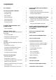
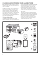
KIT CONTENTS The Alarm System should contain the following devices. Alarm System SL1 SL2 Solar Siren 1 1 Remote Control 1 0 PIR Movement Detectors 1 2 Door / Window Detectors 2 2 Keypad 0 1 Also included: Siren Mounting Template Installation & Operating Manual Installation DVD Fixing Pack Batteries Solar Siren 0 PIR Movement Detector Door / Window Detector Remote Control 1 2 3 4 5 6 1 7 8 9 2 Keypad HEALTH WARNING: 6V/1.
INTRODUCTION AND OVERVIEW SYSTEM ARMING JAMMING DETECTION The system has an Instant-Arm and Delay-Arm mode. In order to detect any attempts to illegally jam the radio channel used by your alarm system, a special jamming detection function is incorporated into the Siren. If this feature is enabled, an alarm will be triggered if the radio channel is jammed continuously for more than 30 seconds or if the system is jammed for more than 3 periods of 10 seconds in a 5 minute period.
PLANNING AND EXTENDING YOUR ALARM SYSTEM the Siren, Keypad, PIR and Magnetic Door / Window Before attempting to install your alarm system it is important to study your security requirements and plan your installation. Detectors for optimum security. Use this as a guide for your installation in conjunction with the detailed positioning requirements for each PIR Movement Detectors are used to protect the main areas of the property, (e.g. lounge, study, hallway and landing).
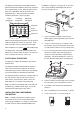
REMOTE CONTROL UNIT (Included in SL1 kit / optional accessory for SL2 kit) The Remote Control Unit(s) is used to Arm in either Instant-Arm or Delay-Arm modes and to Disarm the system. Battery Clip Battery Transmit LED Instant-Arm Delay-Arm Disarm Slide up to operate Personal Attack Switch The Remote Control Unit also incorporates a Personal Attack (PA) switch.
The Keypad is powered by a PP3 Alkaline battery which under normal conditions will have an expected life of approximately 1 year. When the battery level drops, the “LOW BATT” LED on the front of the Keypad will flash. When this occurs the battery should be replaced as soon as possible. Transmit Indicator LED Low Battery Indicator LED installation is complete, (see page 19). If the Siren Unit is being installed and configured for the first time refer to pages 10 - 12.
8. 9. Connect the PP3 alkaline battery to the battery clip and set the jumper link J1 shown in Fig. 1a which is what the keypad is set to normally. Replace the rear cover and refit fixing screws. Do not over-tighten the fixing screws. 4. Enter a new User Access Code of your choice: ? ? ? ? New User Access Code 5. 10. Refit and secure the Keypad onto the wall mounting plate. Do not over-tighten the fixing screw. 1 Press the LED will flash 4 times to confirm the setting has been accepted.
3. Set the jumper link as shown in Fig. 1b. (below). POSITIONING THE SOLAR SIREN 4. Refit the battery and test it by entering the Administrator Access Code 1234. 5. If testing is ok, set the jumper link as shown in Fig. 1a, which is what the keypad is set to normally. The Siren should be located as high as possible in a prominent position on an external wall so that it can be easily seen and heard.
Siren Switch SW3 ALARM TIME ALARM TIME AJ BEEP SOUND C.U. OR SIREN ALARM SOUND 5 ALARM SOUND BEEP SOUND 7.5 Volt DC charging adaptor input Wall mounting plate ON C.U.
ADDING A NEW REMOTE CONTROL OR KEYPAD TO THE SOLAR SIREN IMPORTANT: In order to communicate with the Siren, the ID code of the Remote Control / Keypad needs to be learned by the Siren. Whenever the Siren is being set-up it will automatically enter Service Mode when it is powered-up, ready to learn a new Remote Control / Keypad. Alternatively if the Siren is already in Operating Mode, see page 19 to place the Siren into Service Mode before adding a new Remote Control/Keypad. 11.
MOUNTING THE SOLAR SIREN ON TO THE WALL 16. Hold the clear plastic mounting template supplied in position and mark the positions of the four mounting holes. A spirit level placed on the top edge will help ensure you get the unit level. 17. Undo the fixing screw securing the mounting plate from the bottom edge of the siren and remove the plate. 18. Drill four 6mm holes and fit the wall plugs. 19. Fit the two 30mm fixing screws in the top holes leaving approximately 9mm of the screw protruding. 20.
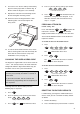
2m - 2.5m INSTALLING AND CONFIGURING THE PIR DETECTORS 1 2 3 4 5 6 7 8 9 10 11 12 Detector Range (metres) Note: If adding a PIR Detector to an installed system, ensure that the Siren is in Service Mode before commencing installation, (see page 19). Remember to switch the Siren back to Operating Mode after installation is complete, (see page 19). 1. Undo and remove the fixing screw from the bottom edge of the PIR Detector, (keep the screw safe for later).
5 minute after which it will automatically revert to normal operation. On initial installation the detector should be configured into Walk Test ready for testing, (i.e. Pressing down SW1 for 2 seconds). SW1 (Test Mode) SW2 SW2 (Tamper) ity sitiv Sen Hi SW3 2 SW SW1 (Test Mode) SW1 Test Mode SW3 1 SW ode tM Tes Press for 2 seconds to activate Walk Test mode Sensitivity Hi Low Low SW3 (Sensitivity) 9.
MAGNETIC DOOR / WINDOW DETECTORS The Magnetic Door / Window Detector comprises of two parts; a Detector and a Magnet. They are designed to be fitted to either doors or windows with the Magnet mounted on the opening part of the door / window and the Detector mounted to the frame. When the protected door or window is opened and the Magnet is moved away from the Detector an alarm will be triggered if the system is armed, (unless the Siren is in Service Mode).
The Detector and Magnet should be mounted using the double sided adhesive pads or screws provided. 6. Switch SW3 is used to enable / disable the internal / external wired magnetic contact. 8mm Note: If mounting the device using the adhesive pads, ensure that the mounting surfaces are clean and dry before mounting. 11mm Location of Key-hole Screw (underside) Detector Magnet SW3 Terminal Block for Additional Wired Magnetic Contact Tamper Switch 4.
TESTING THE DOOR / WINDOW DETECTOR 9. Remove battery cover to activate the tamper switch. As the button is released the LED indicator will illuminate for approximately 1 second to show that the tamper switch has been triggered and a signal is being transmitted. 10. Open the door/window to remove the Magnet from the Detector.
b) Confirm the new device ID code by activating the Tamper Switch again on the PIR/MAG detector within 15 seconds. The siren will produce three short low volume beeps and the Indicator / Learn LEDs will stop flashing and remain ON for 3 seconds after which it will go out. Note: If the valid signal is not received within 15s the Indicator / Learn LEDs will stop flashing and turn off and the siren will produce a single long low volume beep and exit Learn Mode. 3.
TESTING THE SYSTEM The system should be tested at regular intervals (at least every 3 months), to ensure that it is operating correctly. 1. 7. Before commencing testing please ensure the following: Stop the alarm and Disarm the system by entering your User Access Code followed by the ‘DISARM’ button on the Keypad. ? ? ? ? , User Access Code – The Siren is in Operating Mode and Disarmed. – There is no movement or people / pets in any PIR protected area.
OPERATING INSTRUCTIONS When leaving the premises, the system must be Armed. However, before doing so, check that all windows are closed and locked, all protected doors are closed and PIR Detectors are not obstructed. Ensure that pets are restricted to areas not protected by PIR Detectors. ARMING THE SYSTEM IN INSTANT- ARM MODE The system has 2 armed modes, Instant-Arm and Delay-Arm.
DISARMING THE SYSTEM The system can be Disarmed using either the Remote Control or the Keypad as follows: The Alarm will sound until the set alarm duration time expires or the system is Disarmed from the Remote Control or Keypad.
Remote Keypad When the battery is low the ‘low-batt’ LED on the keypad will be illuminated. Note: The Keypad will retain your User Access Code setting for approximately 15 seconds whilst the battery is removed and replaced. If the battery is left disconnected for a longer period, or has been allowed to run completely flat your User Access Code will revert to the factory set code of “1 2 3 4 ” when the new battery is connected. The User Access Code will then need reprogramming as detailed on page 9.
MAINTENANCE Your Alarm System requires very little maintenance. However, a few simple tasks will ensure its continued reliability and operation. IMPORTANT: If, for any reason you have to completely power-down the system (e.g. to move the system to new premises), first put the system into Service Mode before removing the Siren cover and disconnecting the main rechargeable and initial power-up batteries.
TROUBLE SHOOTING Symptom / Recommendation Siren immediately sounds when system armed. 1. Siren tamper switch activated - adjust tamper plunger and ensure that switch fully closes when Siren is mounted. If the wall is excessively uneven, the Siren may need relocating to a more suitable position. 5. Siren rechargeable battery discharged: a. Clean Solar Panel. b. Check age of rechargeable battery - replace if at end of useful life. c. Fit new initial power-up battery and re-power up Siren. 6.
PIR Movement Detector not detecting a person’s movement. 6. If an additional wired Magnetic Contact is connected: 1. Ensure the battery clip is securely connected. a. Check that both contacts are closed. 2. Ensure ‘ID code’ of the Detector has been learnt by the Siren (see page 18). b. Check that additional contact is correctly wired and switch SW3 set to the INT./EXT. position. 3. Sensitivity set too LOW - reset to HIGH sensitivity, (i.e. SW3 to up position).
EXTENDING YOUR ALARM SYSTEM The following additional accessories are available to enhance your system and provide further protection and a higher level of security where required.
COMPONENT SPECIFICATION External Solar Siren Keypad Magnetic Door / Window Detector(s) 0 300 mm 1 2 3 4 5 6 1 7 8 9 2 52 mm 140 125 mm mm 10 12 mm 218 mm ● ● ● ● ● ● ● ● ● ● ● ● ● ● 94 26 mm RF operating frequency: 868MHz Sealed lead acid battery 6V /1.2Ahr Solar Panel 7.