36 Zone Wireless Security System SL5 POWER ALARM STATUS ALARM MEM/ MESSAGE 1 2 3 4 5 7 8 0 LINE STATUS 6 ? 9 ! ESC ENTER Installation & Operating Manual
FOREWORD All devices in this wireless Alarm System are designed and manufactured to provide long reliable service. The system is designed for ease of installation using only conventional domestic tools. However, it is essential that the installer reads and fully understands the advice and procedures contained in this manual and plans the system before proceeding with the installation. During installation, it is important that the procedures described in this manual are followed in sequence.
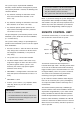
CONTENTS KIT CONTENTS 4 TESTING THE SYSTEM 26 INTRODUCTION AND OVERVIEW 5 5 5 5 5 6 6 6 6 6 6 7 7 7 7 7 FACTORY SETTINGS 31 31 Multiple Users User Access Code System Arming Entry/Exit Delay Zones Zone Lockout Quick Set Event Log Chime Monitoring Latch Key Remote System Control Tamper Protection Jamming Detection Battery Monitoring PLANNING AND EXTENDING YOUR ALARM SYSTEM Typical Installation REMOTE CONTROL UNIT General Information Configuring the Remote Control Testing the Remote Control CONTROL
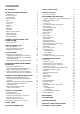
KIT CONTENTS The Alarm System should contain the following devices.
INTRODUCTION AND OVERVIEW MULTIPLE USERS The system allows for up to 6 Users, a Master and a Duress User to be configured. This allows the system Event Log to maintain a record of which users have armed and disarmed the system. Each user will have a different User Access Code. In addition a 4 second voice recorder facility enables the user’s name to be recorded for use with the Latch Key facility. Full Arm Only the Master User has access to the programming functions and is able to configure the system.
The Entry-Delay for each zone may be configured for between 10 to 250 seconds or disabled completely. Note: To conserve power and maximise battery life the PIR Detector will only detect movement if there has been no movement detected within the previous 2 minutes. Consequently the PIR Detector will not become active until the protected area has been free from movement for more than 3 minutes.
LATCH KEY When the system is Disarmed the Latch Key facility, if enabled, will call the first Latch Key phone number and replay the user message (recorded under latch key setup) for the set ‘Play Time’. The recipient must acknowledge the message by pressing the button on their telephone keypad. If the call is unanswered or an acknowledgment is not received then the second Latch Key phone number will be called.
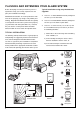
PLANNING AND EXTENDING YOUR ALARM SYSTEM Before attempting to install your Alarm System it is important to study your security requirements and plan your installation accordingly. Typical Installation using only the detectors supplied: PIR Movement Detectors are used to protect the main areas of the property, (e.g. lounge, study, hallway and landing). Magnetic Door/Window Detectors are typically used to protect the main access points to the property, (e.g. front door, back door, patio doors etc).
The system may be expanded with additional detectors, Remote Controls and Keypads to provide even greater protection. However, the following rules should be followed: a. Any detectors covering the main door and the route to the Control Panel should be set on zone 1 only. b. Any detectors covering the remainder of the lower floor should be set on zones 2 to 4 only. c. Any detectors placed upstairs (which are not required when activating Part-Arm1) should be set on zones 5 or 6 only.
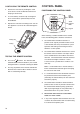
CONFIGURING THE REMOTE CONTROL 1. 2. 3. Remove the rear cover by undoing the small screw on the rear of the Remote Control and keeping it safe for later. CONTROL PANEL POSITIONING THE CONTROL PANEL LCD Display Window Insert the battery under the clip ensuring that the + terminal faces upwards away from the Circuit Board. Replace the rear cover and fixing screw. Do not over tighten the screw as this could damage the thread.
Note: It is recommended that the telephone connection lead is not extended beyond 10 metres before connecting to a telephone master or secondary outlet. DO NOT fix the Control Panel onto or very close to metalwork (i.e. radiators, water pipes, etc) as this could affect the radio range of the device. 4. Fit two 18mm No.4 screws into the top holes until 3mm protrudes from the wall face and hang the Control Panel over these screws using the two keyhole slots in the top corners of the panel casing. 5.
7. Ensure that the Reset Jumper Link (P1) and the External Tamper Switch Jumper Link (P51) are set in the OFF position. inserting the small RJ11 plug into socket marked LINE located on the bottom edge of the Control Panel. If the cable supplied is not long enough to reach a suitable phone point then it will need extending using a coupler and extension lead (not supplied). Jumper Link Jumper Link O.
5. The panel will now listen for a valid signal from a new Remote Control or Keypad. TESTING THE CONTROL PANEL AND REMOTE CONTROL The Panel will remain in Learn Mode for 30s. If a valid signal is not received from a new device within 30s it will automatically exit Learn Mode and return to the top of level 2.0. 1. Press Press ? ? ? , , on to put the 2. Press ENTER to activate Walk Test. Waiting... 3.
2m - 2.5m PASSIVE INFRA-RED (PIR) MOVEMENT DETECTORS PIR Detectors detect movement in a protected area by detecting changes in infra-red radiation levels caused for example when a person moves within or across the PIR’s detection pattern. If movement is detected an alarm will be triggered, (if the system is armed). PIR Detectors will also detect animals, so ensure that pets are not permitted access to areas fitted with PIR Movement Detectors when the system is armed.
4. Rear Cover Flat Wall Mounting Note: The wall plugs supplied with the product are not suitable for plasterboard walls, if mounting the Detector onto plasterboard use appropriate wall plugs. 5. Fixing Screw Fix the rear cover to the wall using the two 18mm No.4 screws and 22mm wall plugs, (a 5mm hole will be required for the wall plugs). Do not over-tighten the screws as this may distort or damage the cover.
On initial installation the detector should be configured into Walk Test ready for testing, (i.e. Pressing down SW1 for 2 seconds). 6. To learn a new detector ID code and link it to the selected zone press 3 . The panel will now listen for a valid signal from a new detector to link to the zone. SW1 (Test Mode) SW1 Test Mode SW3 SW2 The Panel will remain in Learn Mode for 30s.
TESTING A PIR DETECTOR WITH THE CONTROL PANEL 1. 2. Ensure that the system is in Test Mode (see page 13). Use the and buttons to scroll through the menu until ‘Detector Walk Test’ is displayed and press . ENTER Walktest Waiting... will be displayed. Note: If no signal is received by the Control Panel within 10 minutes, the display will return to ‘Detector Walk Test’. 3.
Do not fix the Detector onto or very close to metalwork (i.e. radiators, water pipes, etc) as this could affect the radio range of the device. Note: If mounting the device using the adhesive pads, ensure that the mounting surfaces are clean and dry before mounting. On PVC door / window frames, it may be necessary to space the Detector and Magnet away from the metal surface using a plastic or wooden spacer to achieve the necessary radio range.
6. Switch SW3 is used to enable / disable the internal / external wired magnetic contact. TESTING A MAGNETIC DOOR / WINDOW DETECTOR INDEPENDENTLY 9. 8mm As the button is released the LED indicator will illuminate for approximately 1 second to show that the tamper switch has been triggered and a signal is being transmitted. 11mm Location of Key-hole Screw (underside) SW3 Terminal Block for Additional Wired Magnetic Contact Tamper Switch INT./EXT. Function INT. Internal Contact ON INT./EXT.
6. Activate the Tamper Switch on the MAG detector. Note: If no signal is received by the Control Panel within 10 minutes, the display will return to ‘Detector Walk Test’. Note: If the detector is already linked to the control panel on any other zone then the panel will produce a single long beep and the received signal from the detector will be ignored.
EXTERNAL SOLAR SIREN The Siren is encapsulated within a tough polycarbonate housing that also provides full protection against adverse weather conditions. An LED indicator unit is built into the Siren to act as a visible deterrent and indication that the system is active. The LEDs will slowly and alternately flash whether the system is Armed or Disarmed. When an alarm occurs the LEDs will flash rapidly together.
Siren Switch SW3 ALARM TIME ALARM TIME AJ BEEP SOUND C.U. OR SIREN ALARM SOUND 5 DIP switch 2 marked “AJ” does not function for this system and should be ignored. 6. DIP switch 3 marked “ALARM SOUND” if OFF will prevent the siren from sounding during an alarm, (this will not affect the warning beeps): 8. Siren enabled Siren disabled Switching between Service Mode and Operating Mode generates a series of beeps.
19. Scroll through the Test Mode menu using the and buttons until ‘Wirefree Siren Service ON’ is displayed and press . the Indicator/Learn LEDs will start flashing together rapidly, (once every second). ENTER After 10s the ‘Siren Stop’ signal will automatically be retransmitted by the Control Panel for the siren to confirm the control panels ID code.
DUMMY SIREN INSTALLATION 1. Remove the two screws on the battery compartment cover on the rear of the Dummy Siren and remove the cover. 2. Insert the 4 batteries ensuring correct polarity 3. Refit the battery cover. 6. Drill four 6mm holes and fit the wall plugs. 7. Fit the two 30mm fixing screws in the top holes leaving approximately 9mm of the screw protruding. 8. Fit the keyhole slots in the top of the Dummy Siren over these screws and check that they form a neat fit with minimal movement.
EXTERNAL CONNECTIONS you must first put the system into Test Mode to prevent an alarm occurring. (Optional) External Tamper Switch Jumper Link P51 Terminal Block To do this: , Press 1 2 3 4 , ENTER TAMP GND B+ User Access Code GND BUZ BUT T1 T2 GND T3 T4 N.C. C N.O. GND V+ OUT GND Undo the two fixing screws on the top edge of the Control Panel and open the front cover.
TESTING THE SYSTEM The Control Panel has a built in test facility to enable you to test the system at any time. However it is recommended that the system is tested at regular intervals not exceeding 3 months. With the system in Standby , Press 1 2 3 4 , Detector Walk Test press ENTER Walk Test Waiting...
When the detector is triggered the Control Panel will beep to indicate that a signal has been received and display the zone of the detector that was activated. DETECTOR TEST Before commencing testing please ensure that there is no movement in any PIR protected area for at least 3 minutes, all doors / windows protected by Door / Window Detectors are closed and that all battery covers are correctly fitted. 5. The Control Panel will beep and ‘Zone x : MAG Tamper’ will be displayed.
MAG Detector – Alarm Zone X : MAG Press ENTER During the test the LCD will display: Alarm Siren ON for 5s Stop->ESC MAG Detector – Tamper Zone X : MAG to activate the wired siren for 5s. Press ESC to stop the test early. Tamper Smoke Detector – Alarm Zone X : Smoke Alarm ALARM TEST – AUXILIARY RELAY TEST Scroll through the menu until ‘Auxiliary Relay Test’ is displayed on the LCD. Press to activate the Auxiliary Relay (n.o./n.c.) contacts for 5s.
SPECTRA LIGHTING TESTS Service OFF Scroll through the menu until ‘Spectra Lighting Test’ is displayed on the LCD. Press for 5s. ENTER to activate the linked Spectra lighting During the test the LCD will display: Wait... The siren will produce two short beeps followed 1 second later by a single long beep. The Siren LEDs will flash together in conjunction with the beeps. beeeeeeeeeep …………….…… beep-beep Lights ON for 5s Stop->ESC Press ESC 1 second to stop the test early.
If no acknowledgment signal is received form the Alarm Monitoring Service the panel will beep and the LCD will display: Remote Manager Test....FAIL To stop the test early at the panel press ESC . REMOTE MANAGER TEST (OPTIONAL) – PHONE NUMBER 2 When the call is answered the recorded main alarm message only will be repeatedly replayed for a minimum of 60s after which time the current replay cycle will be completed and the test will end.
FACTORY SETTINGS FACTORY SETTINGS USER CODE SETUP Master User: Users 1-6: Duress Code: LATCH KEY SETUP Status: Selected User Setup: Phone Numbers: OFF OFF (all users) Not programmed ANSWER PHONE SETUP Status: User status: User ID messages: Phone Numbers: OFF All Off Not recorded Not programmed SYSTEM SETUP MENU Alarm Duration: Entry/Exit Delay period: Entry Delay Beeps: Exit Delay Beeps: Wireless Siren: Wired Siren: Auxiliary Relay: Jamming Detection: Zone Lockout: Time: Date: Dial Mode: Remote Phone
PROGRAMMING INSTRUCTIONS With the system in Standby (i.e. with the display showing ‘DISARM READY’). Press , ? ? ? ? , USER SETUP MENU Master User Access Code User 1 Access Code ENTER User 2 Access Code Master User Access Code User 3 Access Code Note: To get to Standby Mode simply press repeatedly until only the POWER LED is illuminated. User 4 Access Code The system is now in Program Mode.
VOICE DIALLER SETUP MENU 1. USER SETUP Phone Numbers press ENTER Record Alarm Messages Replay Alarm Messages 1.0 Master User Code: xxxx 1.1 User 1 Code: xxxx press ENTER Similar for Users 2-6 1.
display for 3s Remotes/Keypads Deleted display for 3s Saving New Device display for 3s Device Confirmed xxxxxx Send PartArm Waiting 15s...
SYSTEM SETUP The parameters in this menu allow the configuration of general system parameters, such as Alarm Duration and control of any hardwired or output relay alarm contacts. This section also contains the basic setup information for the systems telephone dialler interface which must be configured appropriately if any of the telephone based functionality is to be used. Refer to System Setup diagram on page 34. Scroll through the top level programming menu until ‘2. SYSTEM SETUP’ is displayed and press .
Confirm the new device ID code by sending the Disarm signal from the same new Remote Control or Remote Keypad within 15s as follows… Press Press on the Remote Control, or ? ? ? ? , 1 Keypad User Access Code ALARM DURATION Controls the alarm duration of the wireless, internal control panel and wired sirens in the event of an alarm, subject to the On / Off status of the wireless and hard wired sirens which can be independently controlled and disabled. Scroll through the system menu until ‘2.
To change the setting press ENTER . Enter the required delay period (10 - 240s). Press Press ENTER ESC which cannot be de-activated unless the alarm duration is set to 0). to save new setting and exit, or Scroll through the system menu until ‘2.7 Wired Siren’ (and the current setting) is displayed. to exit without saving. To change the setting press ENTRY DELAY BEEPS Allows the systems Entry-Delay warning beeps when arming the system to be switched ON or OFF. ENTER .
ZONE LOCKOUT REMOTE PHONE ACCESS AND CONTROL Prevents a single zone from triggering an alarm more than 3 times before the system is disarmed. (Zone lockout is effective on all zones except 24-HOUR-INTRUDER and FIRE zones which cannot be locked out). If enabled, this allows the system to be remotely controlled via the telephone. Default setting: ON Scroll through the system menu until ‘2.10 Zn Lockout’ (and the current setting) is displayed. To change the setting press ENTER .
ZONE SETUP The parameters in this menu allow each zones specific function to be configured. PROGRAM MODE Code: enter Master User Access Code and press ENTER 3. ZONE SETUP press ENTER Enter Zone(1-36) nn press ENTER Following structure is repeated for each zone only for wired zones 33-36 3.1 Znn Wire Zone only for wirefree zones 1-32 3.2 Znn Name xxxxxxxxxxxxxx 3.1 Znn: xxxxx Edit->Enter press ENTER press ENTER Menus 3.2 - 3.7 repeated 3.3 Znn Type xxxxxxxxxxxxxx 3.
LEARN DETECTOR CODE (zones 1-32 only). Allows a wireless detectors ID code to be learnt and linked to the selected wireless zone. 3.1 Znn: xxxxx Edit->Enter 3.1 Znn: xxxxx 1->Del Learn->3 If the detector is new and not already linked on any security zone the panel will produce two short beeps and the display will show ‘New Device’ and the type or the detected device; (e.g. PIR, MAG or Smoke).
NAME To change the setting press ENTER . This enables a name to be allocated to the zone so it can be identified by its location. Scroll through the menu options, until the required setting is displayed. Available for all zones 1- 36. Only available for wireless zones 1-32 if a detector is linked. Press Press Default setting: No Name Scroll through the Zone menu until ‘3.2 Zxx Name’ (and the current setting) is displayed. To change the setting press ENTER .
PART-ARM 2 Note: For the telephone dialler to operate correctly with the Alarm Monitoring Service the ‘Dialler Mode’ (see System Setup) must be correctly set and programmed. This controls whether the zone is active when Part-Arm 2 is armed. Default setting: OFF (all zones) Scroll through the Zone menu until ‘3.6 Zxx Part-Arm 2’ (and the current setting) is displayed. To change the setting press ENTER Scroll through the menu until ‘6. REMOTE MANAGER SETUP’ is displayed and press ENTER . .
Press Notes: To enter code B, press , 1 To enter code C, press , 2 To enter code D, press , 3 To enter code E, press , 4 To enter code F, press , 5 Press to delete the number under the cursor. Press number. (and hold) to erase the entire Press to save and exit, or Press Press ENTER Press ESC to move the cursor right. ENTER ESC to exit without saving. to save new setting and exit, or After programming all required phone numbers press to return to the top level Voice Dialler menu.
Enter Phone No: enter Tel No (32)... press ENTER enter Tel No (32)... press ENTER press ENTER 5.1.2 Phone No.2 xxxxxxxxxxxxxx Enter Phone No: press ENTER 5.1.1 Phone No.1 xxxxxxxxxxxxxx Playing Playing Playing The recording will then be replayed. During replay the LCD should show... Recording Stop->ESC While recording the LCD should show... press 1 Select YES->1 NO->3 press ENTER 5.2.3 Fire Alarm Message Playing Playing Playing The recording will then be replayed.
LATCH KEY SETUP STATUS The parameters in this menu configures which users the Latch Key feature operates with and the telephone numbers that the system dials when the Latch Key is activated. This controls which users the Latch Key facility will operate with. Note: For Latch Key to operate correctly, the User Access Code, Latch Key Status, User Status, Latch Key Message and Phone number must be correctly set and programmed.
After configuring required users press to the top level Latch Key menu. ESC to return Notes: Press to insert a 3.5 seconds pause in the dialling sequence. User Status Scroll through the system menu until ‘User x Status’ (and the current setting) is displayed. Press to move the cursor left. Press to move the cursor right. To change the setting press Press to delete the number under the cursor. Press Press ENTER . 1 to enable user x with Latch Key, or 3 to disable user x with Latch Key.
FRIEDLAND SPECTRA PLUS LIGHTING SETUP PROGRAM MODE Code: enter Master User Access Code and press ENTER 7. SPECTRA LIGHTING SETUP press ENTER 7.1 Lamp On Time xx minutes 7.2 Lamp On Time xxxxxxxxxxxxxx press ENTER press ENTER Enter (1-20 mins) off 24-hour Time-Controlled enter time press ENTER select menu item press ENTER 7.
OPERATING INSTRUCTIONS When leaving the premises, the system must be Armed. However, before doing so, check that all windows are closed and locked, all protected doors are closed and PIR Detectors are not obstructed. Ensure that pets are restricted to areas not protected by PIR Detectors. The system has 3 arming modes, ARM, Part-Arm 1 and Part-Arm 2. The Part-Arm modes allow for selected zones to be left in a Disarmed state whilst the remainder of the system is Armed.
time a Tamper or PA switch is triggered and each time a detector on an enabled zone is triggered when the panel is armed. If the system has been triggered the ‘ALARM MEM’ LED will flash and the panel will beep every 10 seconds. To stop the LED flashing and panel beeping either a. Press b. Inspect the Event Log to find out the cause of the alarm. ESC 2. Spectra lighting will not be triggered by Smoke Alarm events.
LATCH KEY DEVICE TAMPER If the Latch Key function is enabled and the system is disarmed by a user that is enabled for Latch Key then… The Tamper zone operates on a 24 hour basis. (i.e. Receipt of a Tamper signal form any device will immediately trigger an alarm irrespective of systems armed/disarmed status unless the system is in program or Test modes). 1. The first Latch key phone number will be called (if entered). 2. 10s after the number is dialled the appropriate User ID message will be replayed.
To stop the LED flashing press or access the Event Log to read the event message. ESC To read the event log press 8 from Standby. User Event Messages: User x Arm User x Disarm User x PartArm 1 Use and to manually scroll through the events. Events are displayed starting with event 1 which is the most recent through to event 99. User x PartArm 2 User x Disarm Master Arm Note: The Event Log will not automatically scroll through the display as before.
Double Dial-In for Operation with an External Answer Phone: If the Remote Access and Control feature is to be used and the system is operating in conjunction with an external Answer Phone then 1. 2. Remote Phone Access and Control must be enabled. The number of ‘rings to answer’ for the Control Panel must be greater than that of the external answerphone.
If a further zone 1 alarm event occurs after more than 10 minutes then this event will be transmitted to the AMS. 0m 5m 10m 15m Zn 1 Alarm event Zn 1 Alarm event Zn 2 Alarm event Zn 1 Alarm event Initial Zone 1 event... 2nd Zone 1 event... Initial Zone 2 event... 3rd Zone 1 event... System Armed Zone 1 alarm event sent to AMS occurs within 10 minutes of last Zn 1 event... occurs within 10 minutes of last Zn 1 event...
The dialler sequence can be stopped early by either… a. All numbers have been dialled three times b. The system is disarmed c. A call is acknowledged by the recipient pressing the button on the telephone keypad. Note: The line status warning will not operate if the voice dialler is disabled. The ‘Cancel / Abort’ signal must only be sent if Operating Mode: The siren will produce a single long beep followed 1 second later by two short beeps.
PIR Movement Detector: Under low battery conditions the LED behind the detector lens will flash when movement is detected to indicate that the battery needs to be replaced. Under normal battery conditions the LED does not illuminate unless the PIR Detector is in Walk Test mode. Door / Window Detector: When the Detector is activated, under lowbattery conditions the Transmit LED will be illuminated for approx. 1 second as the door/window is opened.
MAINTENANCE Your Alarm System requires very little maintenance. However, a few simple tasks will ensure its continued reliability and operation. SOLAR SIREN 1. It is recommended that the solar panel on the top of the siren housing should be cleaned at least twice a year, preferably in the Spring and Autumn, using a soft damp cloth. Do not use abrasive, solvent based or aerosol cleaners. Do not attempt to clean inside the unit or allow water to enter the unit.
ALARM RECORD Complete the following information during installation for future reference, when adding to your system and to assist trouble shooting.
You may make a note of your System information below. Remote Manager Phone Numbers (Optional) Phone No. 1: Phone No. 2: System ID No: Voice Dialler Phone Numbers Phone No. 1: Phone No. 2: Phone No. 3: Phone No. 4: Latch Key Phone Numbers Phone No. 1: Phone No. 2: User Access Codes User 1: User 2: User 3: User 4: User 5: User 6: Master User: This information is confidential and should be kept in a safe location.
TROUBLE SHOOTING Symptom / Recommendation Control Unit not working - Power LED OFF or flashing. Siren and Indicator LEDs operating but no alarm at Control Panel. 1. Mains power failure - check if other electrical circuits are operable. 1. Siren’s Tamper switch activated. Check security of Siren fixing to wall and adjustment of antitamper switch to ensure switch is fully depressed. 2. Check that mains adaptor is plugged in and socket is switched ON. 3.
LED on Remote Control not illuminating, or is dim when unit is operated. PIR Detector LED flashes on detection of movement, (device in normal operation mode). 1. Ensure battery is fitted with correct polarity. 1. PIR still in Walk Test Mode for fixed 5 minutes after the PCB button was activated. 2. Ensure battery holder connections are making good contact with the battery. 2. Low battery - replace battery. 3. Battery flat - replace battery. Door / Window Detector not working.
LED on Door / Window Detector illuminating when door or window is opened. 1. Low battery - replace batteries. Voice-Dialler Not Responding to Alarm. 1. Telephone line not connected or faulty - check phone line with another phone. 2. Incorrect phone numbers programmed. Control Unit Not Contacting Remote Manager Service on Alarm. 1. Telephone line not connected or faulty - check phone line with another phone. 2. Dialer Mode incorrectly programmed. 3.
EXTENDING YOUR ALARM SYSTEM The following additional accessories are available to enhance your system and provide further protection and a higher level of security where required.
NOTES 63
COMPONENT SPECIFICATION External Solar Siren Control Panel 300 mm POWER ALARM STATUS ALARM MEM/ MESSAGE 1 2 3 4 5 8 ● ● ● ● ● ● ● ● ● 9 RF operating frequency: 868MHz Sealed lead acid battery 6V /1.2Ahr Solar Panel 7.