
Instructions / Assembly


20
I
M
P
O
R
T
A
N
T
I
M
P
O
R
T
A
N
T
!
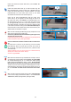
Figure 2.3.1
Figure 2.3.2
STEP 2.3. Drill Holes into Lateral Insect Screen Tracks for Attachment
to Window Side Walls.
2.3.1. Unroll your measuring tape on one of the Lateral Insect Screen Tracks
(J) and using the measuring tape as a guide, MARK the Side Insect Screen
Track (J) about 4 inches (10 cm) from the end. (See Figure 2.3.1.)
Repeat the steps in 2.3.1. for the second Lateral Insect Screen Track
(J)
2.3.2. Drill a hole with a 5/32 in.(3.97mm) drill bit where you marked. (See
Figure 2.3.2.)
Repeat the steps in 2.3.2. for the second Lateral Insect Screen Track
(J)
If the height or installation conditions require it additional holes can be
drilled into the Side Insect Screen Tracks (J) by subdividing the distance
between the two previously drilled holes by half.
STEP 2.4. Prepare and Secure Black Brushweatherstrips.
2.4.1. As detailed in Section 2.2.1. above, please ensure that the
brushweatherstrips inside the Lateral Insect Screen Track (J) are STILL
all 4 aligned at one end, leaving the other end of the Lateral Insect Screen
Track without any brushweatherstrips for the last approximately 2 inches
(5 cm.) of the Lateral Insect Screen Track (J). (Those last 2 inches will
accomodate the Side Insect Screen Stoppers (L) inserted by you in Step
2.4.2. below). The side of the Lateral Insect Screen Tracks (J) that has
NO brushweatherstrip will become the bottom of retractable insect screen
frame structure resting on the window Sill.
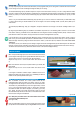
2.4.2. With pliers pinch both ends of the Lateral Insect Screen Tracks
(J) where the brushweatherstrip lies.
(See Figure 2.4.2.)
Pinch the brushweather strip at the TOP of the Side Insect Screen Track
(the part where the brushweather strips are aligned NOT the bottom where
STEP 2.2 TIPS
You may temporarily tape the Lateral Insect Side Tracks (J and J) together while you are cutting them to minimize their movement while
you are cutting, and to ensure maintaining their alignment while you are cutting.
The enclosed Measuring Tape (K) should be layed onto atop the Lateral Insect Screen Track (J) to act as a Cutting Reference Guide,
as shown in Figure 2.2.2B. Like the allowance calculating factory pre-adhered measuring reference tape guide on the Screen Cartridge
Header (A1) in Step 1.2 in section above, the Measuring Tape (K) enclosed makes relevant allowance calculations for you so you don't
have to.
That is to say, the enclosed Reference Measuring Tape (K) allows you to cut at the mark of the measurement you determined in Step
2.1 above, without having to calculate allowances for how the length of the Screen Cartridge Header A (A1/A2) affects (adds to) the
measurement.
The enclosed paper Measuring Tape (K) is designed to incorporate allowances for the length of the Screen Cartridge Header A (A1/
A2).
By using the paper Measuring Tape (K) included in our Hardware components kit, as the indicator guide as to where to cut the Lateral
Insect Screen Tracks (J) you will NOT have to make allowances for the length of the Screen Cartridge Header A (A1/A2). and/or for the the
points where the Lateral Insect Screen Track (J) intersects into the Screen Cartridge Header A (A1/A2)
If you do NOT want to use the enclosed paper Measuring Tape (K) to determine where to cut Lateral Insect Screen Tracks (J) and you
prefer to use your own household tape measure to determine where to cut the Lateral Insect Screen Tracks (J) to fit into your window's
Side Jamb height. Proceed by cutting both Lateral Insect Screen Tracks (J) 1.88 inches (48 mm) LESS than the overall window INSIDE
JAMB height.
The 1.88 inch ( 48 mm) is an allowance you are making for length of the Screen Cartridge Header (A) that will already be in the Head Jamb
taking up 1.88 inch in length and making up the balance of the Inside Jamb height when you install the Lateral Insect Screen Tracks (J).
The Lateral Insect Screen Tracks (J) will intersect with the bottom of the Screen Cartridge Header (A).
Figure 2.4.2