Retro Instruments, Inc.
Retro Instruments, Inc. 176 Tube Limiting Amplifier User’s Manual 2008 Retro Instruments, Inc. P.O.
Manual Revisions Revision Print Date Initial Release December 29, 2008 Notices 2008 Retro Instruments, Inc. All rights reserved. No part of this document may be reproduced, transmitted, transcribed, stored in a retrieval system, or translated into any language in any form by any means without the written authorization of Retro Instruments, Inc. Printed in U.S.A. User Manual Part Number – 176001-01 XLR, RCA, Xcelite, UA are trademarks of their respective companies.
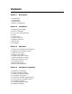
Contents Section 1 Description 1.1 Your Limiter 1.2 Applications 1.3 Specifications 1.4 Safety Considerations Section 2 Installation 2.1 Operating Environment 2.2 Power Connections 2.2.1 AC Line Voltage Selection 2.2.2 Fuse 2.2.3 Line Cord 2.3 Input Connection 2.4 Output Connection 2.5 Stereo Link 2.6 Grounding Section 3 Operation 3.1 Power Switch, Indicators and Interlock 3.2 Amplifier Active/Bypass Switch 3.3 Input Level Control 3.3 Output Level Control 3.4 Compression Ratio Control 3.
4.1.9 Test Facilities 4.2 Power Supply Circuit Board 4.2.1 Mains Input 4.2.2 Power Transformer 4.2.3 5Y3 High Voltage Rectifier 4.2.4 OB2 Gas Discharge Tube 4.2.5 Bleeder Resistor Section 5 5.1 5.2 5.3 5.4 5.5 5.6 5.7 Gain Reduction Meter Zero Internal Balance Test Switch Balancing the 6BC8 Gain Reduction Stage Balancing the Amplifier Stage Noise and Distortion Tests Frequency Response Tests Hum and Microphonics Section 6 6.1 6.
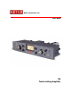
Section 1 Description This section provides a general description of the 176 Tube Limiting Amplifier. Please review this information before installing or operating the 176. 1.1 Your Limiter The 176 Tube Limiting Amplifier is designed to provide the quintessential character of vintage tube compression in the modern recording studio environment. It is modeled after the superb UA 176 limiter and adds new features and conveniences.
1.5 Safety Considerations The Retro 176 is to be used in a metal equipment rack with adequate ventilation. The vacuum tubes become hot. The AC mains power should be disconnected prior to servicing. For safety, the front door of the 176 is equipped with an interlock switch that interrupts the AC mains power when the door is opened. This switch should not be defeated. Only trained technicians should open the front door to gain access to the internal adjustments.
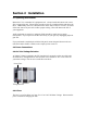
Section 2 Installation 2.1 Operating Environment Mount the 176 in a standard 19” equipment rack. Always install the bottom rack screws first to support the unit. Please allow room above the top ventilation holes and above the tubes. Additionally, there are ventilation holes on the sides to draw in cool air. Be aware of the heat sources in your rack to allow proper cooling. Heat will shorten the life of your equipment.
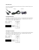
2.2.3 Line Cord You can use a compatible IEC power cable for 100-120 Volts or 200-240 Volts per your country’s specification. USA Europe Australia 2.3 Input Connection Audio Input is a standard female XLR connector. It is transformer balanced and floating, meaning there is no path to ground from pin 2 and 3. Unbalanced sources connect the center conductor to pin 2 and the shield to pin 3. 2.4 Output Connection Audio Output is a standard Male XLR connector.
2.5 Stereo Link An RCA jack on the rear panel allows strapping of multiple 176 limiters. An optional stereo link panel is available to couple two units. Coupling Jack 2.6 Grounding The 176 is primarily grounded through the AC Mains. For safety, do not disable the AC ground. The chassis is also grounded through the rack ears to the rack. The XLR connectors are grounded on pin 1. Pin 1 is only used to drain the shield of the audio cable on one end of the cable.
Section 3 Operation 3.1 Power Switch, Indicators and Interlock Upon initial installation, apply power. The red indicator and meter should light immediately. If not, check power connections. Make sure the front door is securely closed. Check that the voltage selector is set to the proper voltage. Finally, check the fuse. If the fuse is blown, the likely cause is the fuse itself or a damaged 5Y3 rectifier tube. After a minute the meter should read near zero in the GR setting. The 176 is now ready to use. 3.
the various ratio settings when doing approximately 10 dB of gain reduction, however at less amounts of gain reduction the lower ratio settings will start compression sooner than higher ratios. 3.5 Attack and Release Controls The Attack and Release controls determine how quickly the dynamic range is adjusted by the compression. The effect of these controls can be heard as well as observed in the meter action. The Retro 176 has extended adjustment of the attack and release characteristics.
3.8 Meter Select Switch The Meter Select switch provides metering of the Input and Output levels and the Gain Reduction. The Input and Output meters are referenced to a standard operating level of +4 dBm. It is simple to check your input and output levels for easy setup and A/B comparisons with the Bypass switch. The Input Meter is fed directly from the Input XLR. The Output Meter is fed directly from the 176 Output Control before the Amplifier Bypass switch. Normally the meter is kept in the GR position.
Section 4 Principles of Operation 4.1 Amplifier Circuit Board 4.1.1 Input Transformer Stage The Input from the Female XLR Input connector feeds the bypass side of the Bypass switch and the input pad and input transformer. The input pad provides 20 dB of loss and transforms the 600 Ohm input to the proper 120 Ohm transformer impedance. The input transformer feeds the grids of the 6BC8 variable-mu gain reduction stage through the Input Level control in a balanced 200K Ohm arrangement. 4.1.
4.1.6 Asymmetry Switch The asymmetry switch raises the bias and threshold of the negative or positive side of the detector depending on the position of the switch. 4.1.7 Sidechain Highpass Filter The Sidechain HPF applies additional resistance across the detector input coupling capacitors effectively creating a first order highpass filter. The filter is disabled through a switch when the filter control is set at minimum. 4.1.
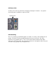
4.3.4 0B2 Gas Discharge Tube The 0B2 is a cold-cathode, glow discharge tube. In combination with a 10K Ohm resistor it provides a regulated 108 Volts to the 6BC8 gain reduction stage. It will glow orange or purple depending on the variety. This tube can fail two ways; it stops glowing and the gain reduction meter rises to +3, or the light dances in the tube causing a rumble or squeal in the audio signal. With normal gain reduction this tube will dim slightly. This is normal. 4.3.
Section 5 Alignment and Maintenance Balance Test Switch VR1 VR2 VR3 Meter Zero Cathode Bal. Plate Bal. VR4 Amp. Bal. All adjustments should be performed by a qualified technician. 5.1 Gain Reduction Meter Zero Use a small Xcelite Greenie or precision adjustment tool to make internal adjustments. The Gain Reduction Meter can be adjusted to zero to compensate for normal aging of components over time.
Adjust VR3 for minimum indication on the VU meter. Sometimes this will not be a full dip. Only an extremely matched 6BC8 will dip fully. Set Balance Test Switch to Up (Static Test). Adjust VR2 for minimum indication on the VU meter. The meter should dip to −20 dB at the null. Continue to the next step to balance the amplifier stage. 5.4 Balancing the Amplifier Stage Only perform this adjustment after balancing the 6BC8 stage. Continue by setting the Interstage Switch to OUT.
squeal or make other space-like sounds. Mostly, they will make sound when you tap them. A healthy tube may make a tink or bonk sound or nothing at all. An excessively microphonic tube will make spastic sounds when tapped which can help isolate an intermittently noisy tube. The 6BC8 will always exhibit some microphonics because it is the first stage of amplification and has a relatively tiny signal passing through it.
Section 6 Schematics and Drawings 6.
Section 7 Support and Service Retro Instruments provides all levels of support and service for your product. 7.1 Service The Product Warranty outlines our responsibilities for defective products. We also provide parts and service beyond the warranty period. Before returning a product for repair, contact our service department by telephone at 209810-3344 or contact us through our service page at http://retroinstruments.com/ We will give you instructions how to return your product for service.
7.4 Warranty Retro Instruments products are warranted to be free of all defects in material and workmanship for one year from the date of purchase. Within the period of this warranty, Retro Instruments will replace or repair at no charge at its service facility any part which is defective in material or workmanship.
7.5 Factory Service Instructions To obtain factory service, complete this page and include it with the unit.