
User`s manual


Section 3 Operation
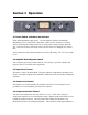
3.1 Power Switch, Indicators and Interlock
Upon initial installation, apply power. The red indicator and meter should light
immediately. If not, check power connections. Make sure the front door is securely
closed. Check that the voltage selector is set to the proper voltage. Finally, check the
fuse. If the fuse is blown, the likely cause is the fuse itself or a damaged 5Y3 rectifier
tube.
After a minute the meter should read near zero in the GR setting. The 176 is now ready
to use.
3.2 Amplifier Active/Bypass Switch
This switch lets you easily evaluate what the 176 is doing. It provides a hard-wired
bypass of the 176 for instant A/B comparisons.
3.3 Input Level Control
The Retro 176 has a fixed threshold. The gain reduction is adjusted by the Input Level
control. The input is optimized for standard +4 dBm line levels to provide 0-20 dB gain
reduction.
3.3 Output Level Control
The Output Level control matches the Output Level of the 176 to the Input Level or
provides less or more amplifier gain as the user requires.
3.4 Compression Ratio Control
The ratio can be adjusted in four steps from 2:1 to 12:1. Lower ratios will put a
compression signature over a wider dynamic range. Higher compression ratios are best
to hold the signal level down. The ratio control also changes the threshold. The
threshold axis point is at 10 dB gain reduction. This results in similar gain reduction at