
User`s manual


Section 5 Alignment and Maintenance
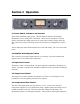
Balance Test Switch
VR1 VR2 VR3 VR4
Meter Zero Cathode Bal. Plate Bal. Amp. Bal.
All adjustments should be performed by a qualified technician.
5.1 Gain Reduction Meter Zero
Use a small Xcelite Greenie or precision adjustment tool to make internal adjustments.
The Gain Reduction Meter can be adjusted to zero to compensate for normal aging of
components over time. With no input applied and the release control set to 50, adjust
VR1 so that the meter sits exactly at the 0 dB mark. The Release control can have a
slight effect on the zeroing. The asymmetry switch should have no effect on the meter
zero. If it does, the 6AL5 tube may be at fault.
5.2 Internal Balance Test Switch
The Internal Balance Test Switch has three settings. For normal operation, it must be in
the center position. The Top position (static test) is used to set VR2 and VR4. The
Bottom position (dynamic test) is used to set VR3. The Meter Zero VR1 may have to be
trimmed after balancing.
5.3 Balancing the 6BC8 Gain Reduction Stage
Poor balance will be apparent on compression attack, causing a ripple sound or a thump.
Set the Meter Selector to Output. Set Interstage Switch to IN. Set Release to 100 (fast).
Set Output Level to 100 (full). Set Balance Test Switch to Up (Static Test).
Adjust VR2 for minimum indication on the VU meter.
Set Balance Test Switch to the Bottom position.