
Installation Guide
Soft-Close Pullout with
Tandem slides with BluMotion
T-448SC-0412
Center line of Cabinet Opening
Recommended Screw and Pilot
Hole Location (8) Places
* Fold Template along
this edge to t
cabinet opening.
* Use this side for
8” Wide Pullout
Front edge of paper
to front of cabinet
(or front of face frame)
TOOLS REQUIRED:
ESTIMATED ASSEMBLY
TIME:
30 MIN
CARE AND MAINTENANCE:
CLEAN WITH A DAMP CLOTH
AND WIPE PARTS DRY
PARTS LIST:
SLIDES AND SLIDE STRAPS
PULLOUT CHASSIS
4 #6 X ½” FLAT HEAD SCREWS
10 #6 X 1” FLAT HEAD SCREWS
ADJUSTABLE RUB BUSHING KIT
2 DOOR BUMPERS
3/32”
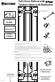
1) Assemble the mounting straps (Fig 1) and attach them to the Blum Tandem slides by snapping the plastic feet into the appropriate holes.
(See Fig 1b)
2) Using the mounting template locations, pre drill 8 holes using a 3/32” drill bit.
3) Assemble the slide assembly to the oor of the cabinet using the (8) #6 x 1” at head screws. (Note: that the screws use the inner set of
holes on the plastic feet. (See Fig 2)
4) With the slides in the fully closed position the pullout chassis can now be slid into place fully inserted into the cabinet. When the unit is
pushed to the fully closed location the front release levers will engage the slides and the unit can be fully cycled.
5) Loosen the machine screws at the top back wall of the unit to allow the rear stop to oat freely. (See Fig. 3). Raise the rear stop until it
catches the rear of the face frame (if frameless application, a block may need to be added to allow the stop to work properly). Once the
stop is at the right height, the machine screws can be tightened. (Note: Once in place you can permanently secure the location using
the pre-drilled pilot holes and the (2) #6 x 1” at head screws provided.)
6) Rubber bumpers are provided to place at the top of the rear stop between the face frame and the stop to deaden the noise. (See Fig 3)
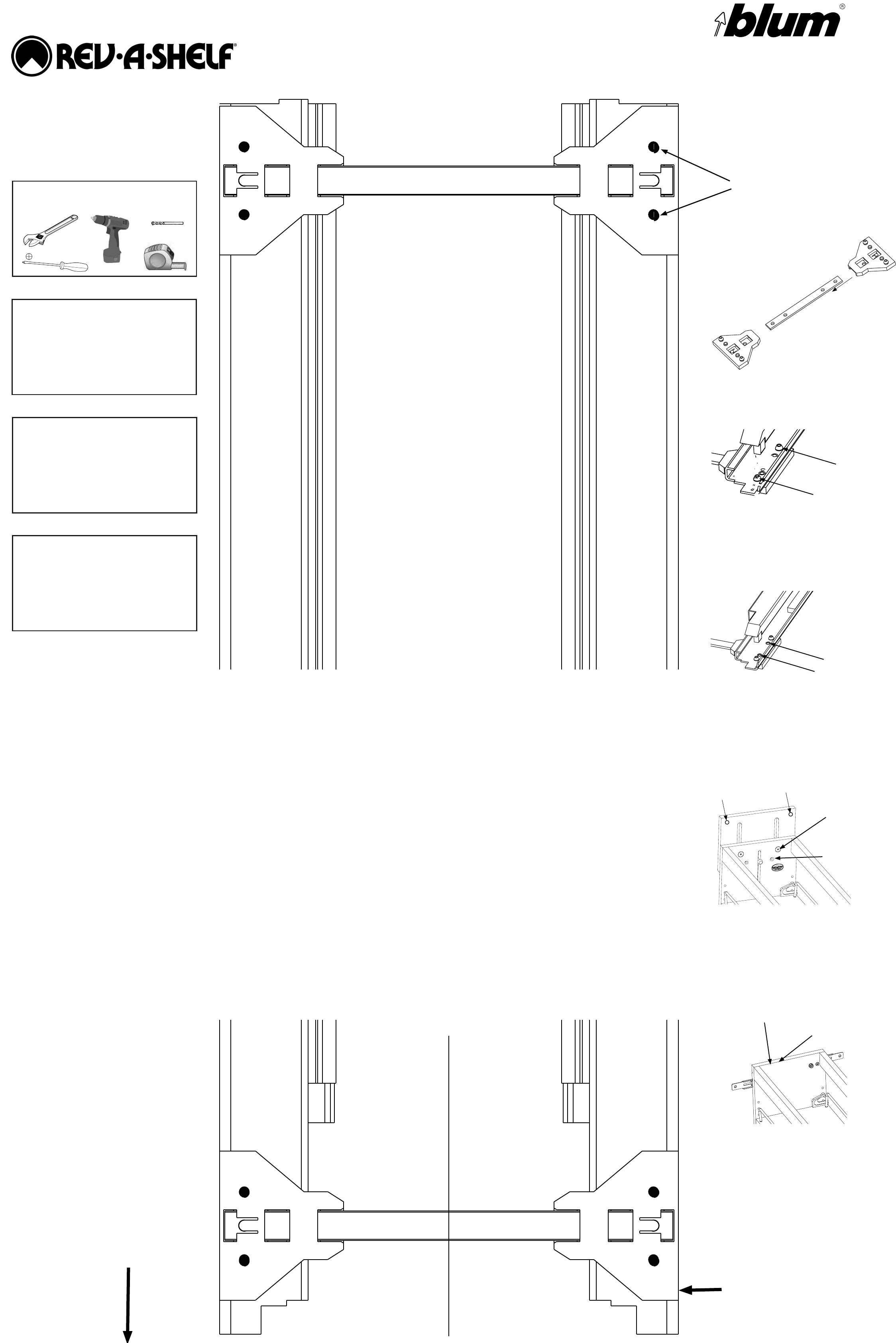
Attaching the cabinet door
1) Loosen the (4) lock nuts (3/8” wrench) inside the front wall of the unit. (See Fig 4)
2) Pull the Adjustable Door Mounting Brackets to ensure that you are mounting to the “thick” portion of the cabinet door. (Front of pull out
should line up with front of face frame).
3) Use the (4) #6 x ½” at head screws provided to attach the door to the pullout unit.
4) If the door needs to be tilted to lay ush against the face frame, loosen the 8mm nuts and turn the “T-Nut” screws so that it pushes against
the metal bracket. Each corner can be adjusted independently. (Note: It is recommended that door bumpers be used on each corner to
ensure quiet operation)
Install rub bushings using enclosed kit and instructions (Note: Chassis may need to be removed for proper installation)
Fig 1
Fig 2
Fig 3
Fig 4
Loosen
For Permanent
Attachment
T-Nut Screw for
Tilt Adjustment
Suggested
Bumper Location
Lock Nut
Fig 1b