
Installation Guide
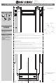

Center line of Cabinet Opening
Screw and Pilot Hole
Location (4) Places
Fold Template along this edge to t
cabinet opening.
Front edge of paper
to front of cabinet
(or front of face frame)
Fig 1
T-Nut Screw for
Tilt Adjustment
Lock Nut
12400 Earl Jones Way
Louisville, KY 40299
rev-a-shelf.com
Customer Service: 800-626-1126
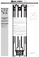
8” SOFT-CLOSE PULLOUT WITH BLUM TANDEM SLIDES WITH BLUMOTION
TOOLS REQUIRED:
30 MIN
ESTIMATED ASSEMBLY TIME:
CARE AND MAINTENANCE:
Clean with a damp cloth and
wipe parts dry.
PARTS LIST
- Frame/Slide assembly
- (4) #6 x ½” at head screw
- (4) #8 x ¾” deep thread pan
head screw
- Template
- Adjustable Rub Bushing Kit
3
32
Attaching slide to cabinet
1) Using the mounting template locations, pre drill 4 holes using a 3/32” drill bit.
2)Removetemplateandattachtheslideassemblytotheoorofthecabinetusing(4)#8x¾”deepthread
screws provided.
3) With the slides in the fully closed position, place the frame on the slides and push back until you feel the
slides engage the locking devices (you will hear a click sound). Fully cycle the frame a few times.
Attaching the cabinet door
1) Loosenthe(4)locknuts(3/8”wrench)insidethefrontwalloftheunit.(SeeFig1)
2) Pull the Adjustable Door Mounting Brackets to ensure that you are mounting to the “thick” portion of the
cabinet door. (Front of pull out should line up with front of face frame).
3) Usethe(4)#6x½”atheadscrewsprovidedtoattachthedoortothepulloutunit.
4) Ifthedoorneedstobetiltedtolayushagainstthefaceframe,loosenthe8mmnutsandturnthe“T-Nut”
screws so that it pushes against the metal bracket. Each corner can be adjusted independently. (Note: It is
recommended that door bumpers be used on each corner to ensure quiet operation)
Install rub bushings using enclosed kit and instructions (Note: Chassis may need to be removed for proper installation)
T-448SC-1116