
Installation Guide
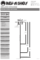

TOOLS REQUIRED:
45 MIN
ESTIMATED ASSEMBLY TIME:
CARE AND MAINTENANCE:
PARTS LIST
STEP 1
STEP 2
STEP 3
STEP 4
STEP 5
STEP 6
STEP 7
Clean with a damp cloth and wipe parts dry.
- (2) Wood D-Shaped Trays
- (1) 22-1/2” Lower Shaft
- (1) 9-1/4” Upper Shaft
- (2) Positioner Base Assemblies
- (1) Top Pivot
- (4) #8x1/2” Truss Head Screws
- (4) #8x3/4” Oval Head Screws
- (1) 1/4-20”x5/16” Shaft Locking Screw
- (3) #8x3/4” Machine Screws
- (2) Top Shelf Supports
- (2) Bottom Shelf Supports
Insert bottom shelf support in tray from bottom with
keyway facing rear of tray. Position top shelf support
on top of tray with keyway facing rear of tray.
Using #2 phillips bit, install (3) #8x 3/4” machine screws
through top shelf support into bottom shelf support
and tighten.
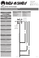
Locate mounting holes with template, pre-drill holes
using 1/8” drill bit. Using the #2 phillips bit, install the
positioner base assembly on cabinet oor with (4) #8x
3/4” oval head screws.
NOTE: Shaft locking screw must face cabinet opening.
Locate mounting holes with template, pre-drill holes
using 1/8” drill bit. Using #2 phillips bit, install the
upper pivot on cabinet top with (4) #8x 1/2” truss head
screws.
Slide the second positioner base assembly onto
the shaft approximately 15” from the bottom and
temporarily tighten using a #3 phillips bit. Next,
starting at the top of the shaft slide on the upper shelf,
then starting at the bottom of the shaft slide on the
lower shelf.
Slide the 9-1/4” upper shaft into the upper end of
the 22-1/2” lower shaft. Loosely install locking screw
into upper end of the lower shaft. Insert lower shaft
into bottom positioner base assembly and tighten the
positioner base assembly locking screw using a #3
phillips bit. Lift upper shaft to engage in the top pivot
and tighten the locking screw using a #3 phillips bit.
Allow bottom shelf to rest on the bottom positioner
base. Adjust upper shelf by grasping and supporting
upper positioner assembly while loosening locking
screw. Rotate positioner and shelf into alignment and
securely tighten locking screws.
(3 mm)
1
8
Bottom positioner
assembly hole pattern
Front of cabinet- 20” (508 mm)
Front of cabinet- 28” (711 mm)
Front of cabinet- 32” (813 mm)
8-5/8”
(219 mm)
12-1/16”
(306 mm)
13-3/4”
(350 mm)
Upper pivot
hole pattern
T-LD-4NW-272-1117
12400 Earl Jones Way
Louisville, KY 40299
rev-a-shelf.com
Customer Service: 800-626-1126
NATURAL WOOD LAZY SUSAN
INSTALLATION INSTRUCTIONS: NATURAL WOOD LAZY SUSAN
Center line of cabinet opening
#2#3