
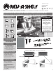
Instructions / Assembly

2
Customer Service: 800-626-1126 | rev-a-shelf.com
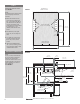
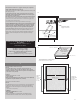
ADJUSTING SPRING TENSION
SEE FIGURE C & D
The Heavy Duty Mixer Lift has
three adjustable spring tension
settings:
1. 0–20 lbs. (0 kg–9.07 kg),
2. 20–30 lbs. (9.07 kg–13.6 kg)
3. 30–60 lbs. (13.6 kg–27.2 kg)
Releasing the 12 mm box end wrench
being used to hold the spring loaded side-
mounting brackets before securely fastening
the removed bolt can cause serious injury.
PLEASE ADJUST WITH CAUTION
WARNING
FIGURE C
VIEW FROM INSIDE THE CABINET
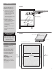
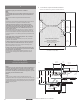
FIGURE B
4-1/2”
(114 mm)
1-1/2”(38 mm) FACE RAIL
TO INSURE PROPER ALIGNMENT, USE A
LEVEL TO ESTABLISH THIS LINE
1-1/2” (38 mm) COUNTER TOP
DRILL (2) 3/32” (2 mm) PILOT HOLES
11-3/8” (289 mm)
3/8”
(10 mm)
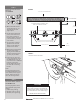
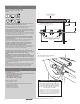
INSTALLING SIDE MOUNTING
BRACKETS
SEE FIGURE B
#2
3
32
3
mm
A. Mark and Pre-drill two 3/32”
(3 mm) pilot holes 1/2” (13
mm) deep into the side
support panel.
B. The rst hole should be 3/8”
(10 mm) from inside of face
frame (front of cabinet on
frameless cabinet), and 4-1/2”
(114 mm) down from the top
of the cabinet.
C. The second hole is located
parallel from the rst hole
location 11-3/8” (289 mm)
towards rear of cabinet.
D. Mount side mounting bracket
to cabinet side panel by
aligning outside middle hole
locations with the holes that
you have just pre-drilled.
E. Fasten with two- #10 x 3/4”
(19 mm) wood screws. Fasten
six additional #10 x 3/4” (19
mm) wood screws to additional
locations on side mount
bracket. Repeat this step for
the other side of mounting
bracket.
NOTE
Side mounting brackets must
be installed parallel with the top
of the cabinet (level) for proper
function. Repeat this step for
other side mounting bracket.
STEP 1
STEP 2
1-1/2”(38 mm) COUNTERTOP