
Instructions / Assembly

4
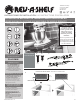
Customer Service: 800-626-1126 | rev-a-shelf.com
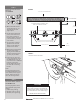
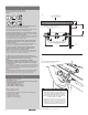
MOUNTING MIXER LIFT SHELF
SEE FIGURE E
NOTE
Pre-drilling rst four hole locations
will ensure proper function of
mixer lift.
A. Mark hole locations for the
front screws by measuring in
3/4” (19 mm) from the side of
the shelf and 8-1/4” (209 mm)
from the front edge of the
shelf. Mark rear screw locations
by measuring up 7-1/2”
(190mm) from the rst set of
marks.
B. Pre-drill 3/32” (2 mm) pilot
holes 1/2” (12 mm) deep into
shelf.
C. Turn shelf over and mount to
mounting brackets with four
#10 x 1/2” (12 mm) wood
screws.
D. Attach four additional #10 x
1/2” (12 mm) mounting screws
from underneath shelf to other
available hole locations.
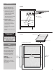
“D” MINUS 1-1/4”(32 mm)
UNDERSIDE OF
MIXER LIFT SHELF
FRONT EDGE OF
MIXER LIFT SHELF
7-1/2”
(191 mm)
8-1/4”
(210 mm)
3/4”
(19 mm)
20-1/2”
(521 mm)
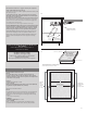
FIGURE F
LAYOUT AND DRILL
(4) 3/32” (3 mm) HOLES
STEP 4
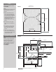
CLEARANCE DIMENSIONS
NOTE
4-1/2” (114 mm) measured from
the top of cabinet is adequate
clearance for most kitchen
accessories. Side mounts can be
positioned higher if using lift for
smaller appliances or lower for
taller appliances.
SEE FIGURE G
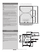
FIGURE G
4-15/16”
(125 mm)
1-7/8”
(48 mm)
11-3/8”
(289 mm)
2-1/8” (54 mm)
22-7/16”
(570 mm)
1-3/16” (30 mm)
8-15/16”
(227 mm)
15-13/16”
(401 mm)
20-1/2”
(521 mm)
14-9/16”
(370 mm)
3/8”
(9 mm)
17-9/16”
(446 mm)
1-1/2”
(38 mm)
18-11/16”
(475 mm)
4 1/2” (114 mm)
3/4”
(20 mm)
4-3/8” (112 mm)
LOWEST POINT