
Instruction Manual

790 Rowntree Dairy Road, Woodbridge ON, Canada L4L 5V3
Tel: 905-851-6701 Fax: 905-851-8376 info@reversomatic.com
w w w . r e v e r s o m a t i c . c o m
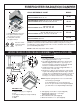
STEEL JOIST INSTALLATION
MATERIAL LIST:
1. Fan
2. FireFighter Damper (Factory Installed)
3. Ceiling Tile
4. Ceiling Tile Support Angle 3/4” x 1/2” 22ga.
(Optional Not Supplied)
5. Grille
6. Self-tapping screws #8 x 1/2”
(Not Supplied)
7. U-channel 18 Ga. (Not Supplied)
8. 1/4” x 3/4” Bolts (Not Supplied)
9. Support Strap (2 pcs. Supplied)
9
4
2
7
7
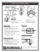
Fig.1
7
8
Fig.2
C
½”
3
4
6
2
1
5
3
4
FAN INSTALLATION:
1. Assemble Support Strap (9) to fan housing with
self-tapping screw #8 x ½”.
2. Assemble Ceiling Tile Support Angle (4) to fan
housing with self-tapping screw #8 x ½” spaced
every 6”.
3. All ceiling tile supported on angle (4) must be
trimmed as per Fig. 2. Allowing necessary expansion
as per dimension “C”, minimum 1/8” & maximum 1/4”.
4. Secure “U” channel (7) to steel joist.
5. Install fan housing as shown in Fig.1.
NOTE: Ceiling tile opening must be cut to accommodate
fan housing as per Fig. 2
ELECTRICAL INSTALLATIONS:
1. Connect motor as per nameplate diagram to correct
power supply.
2. Install all wiring, protection and grounding in
accordance with the National Electrical Code (NEC)
and all local requirements.
3. Follow all local electrical and safety codes, as well
as the National Electrical Code (NEC) and the
Occupational Safety and Health Act (OSHA).
2 SPEED MOTOR WIRING DIAGRAM
2 SPEED
MOTOR
WHITE
WHITE
RED
RED
BLACK
BLACK
120 VAC
60 HZ
TOGGLE SWITCH
3 position-on/off/on
(optional)
GREEN
LOW Speed: White - Red
HIGH Speed: White - Black
Model:
CF 170-2 QCF-125CO
RS 90-2
RS 90-2FF
Motor
115 Volt
Thermoprotected
Wire Nut
Plug
Receptacle
Junction Box
Ground Screw
Ground
Wire
Black
White
WIRING DIAGRAM: