
Use and Care Manual


User’s Manual
4
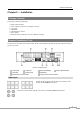
Audio Out
NOTE: It is the user’s responsibility to determine if local laws and regulations permit recording audio.
Alarm Input/Output
AI 1 to 16 (Alarm-In): You can use external devices to signal the DVR to react to events. Mechanical or electrical
switches can be wired to the AI (Alarm-In) and GND (Ground) connectors. The threshold voltage of electrical
switches for NC (Normally Closed) is above 2.4V and for NO (Normally Open) is below 0.3V, and should be stable
at least 0.5 seconds to be detected. The voltage range of alarm input is from 0V to 5V. See Chapter 3 ─ Configuration
for configuring alarm input.
GND (Ground): Connect the ground side of the Alarm input and/or alarm output to the GND connector.
NOTE: All the connectors marked GND are common.
NO (Normally Open): Connect the device to the COM and NO (Normally Open) connector. NO is a relay output
which sinks 1A@30VDC. See Chapter 3 ─ Configuration for configuring alarm output.
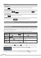
Connector Pin Outs:
AI (1 to 16)
Alarm Inputs 1 to 16
GND
Chassis Ground
COM
Relay Common
NO
Relay Alarm Out (Normally Open)
Factory Reset Switch
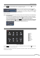
The DVR has a Factory Reset switch to the left of the HDMI connector on the rear panel. This
switch will only be used on the rare occasions that you want to return all the settings to the original
factory settings.
CAUTION: When using the Factory Reset, you will lose any settings you have saved.
To reset the unit, you will need a straightened paperclip:
1. Turn the DVR off.
2. Turn it on again.
3. While the DVR is initializing, the front panel LEDs will blink. When the front panel LEDs blink, poke the
straightened paperclip into the unlabeled hole to the left of the HDMI connector.
4. Hold the reset switch until the DVR’s internal buzzer sounds twice.
5. Release the reset switch. All of the DVR’s settings are now at the original settings it had when it left the factory.
Video Out
An HDMI (High-Definition Multimedia Interface) connector is provided so that you can use
an HDMI monitor as your main monitor.
A VGA connector is provided so that you can use a standard, multi-sync computer monitor
as your main monitor. Use the cable supplied with your monitor to connect it to the DVR.
Connect Audio Out to your amplifier using the RCA jack. If supported, connect the audio sources to the
audio input connector of the observation cameras that are connected to the modular RJ-12 connectors of
the DVR. Refer to the observation camera manual for configuring the Audio In connection. Your DVR
can record audio from up to 12 sources.
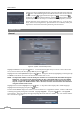
NOTE: To make connections on the Alarm Connector Strip, press
and hold the button and insert the wire in the hole below the button.
After releasing the button, tug gently on the wire to make certain it is
connected. To disconnect a wire, press and hold the button above
the wire and pull out the wire.