4 & 8 Channel Digital Video Recorder WARNING RISK OF ELECTRIC SHOCK DO NOT OPEN WARNING: TO REDUCE THE RISK OF ELECTRIC SHOCK, DO NOT REMOVE COVER (OR BACK). NO USER-SERVICEABLE PARTS INSIDE. REFER SERVICING TO QUALIFIED SERVICE PERSONNEL. The lightning flash with arrowhead symbol, within an equilateral triangle, is intended to alert the user to the presence of uninsulated "dangerous voltage" within the product’s enclosure that may be of sufficient magnitude to constitute a risk of electric shock.
User’s Manual Important Safeguards 1. Read Instructions All the safety and operating instructions should be read before the appliance is operated. 10. Overloading Do not overload wall outlets and extension cords as this can result in the risk of fire or electric shock. 2. Retain Instructions The safety and operating instructions should be retained for future reference. 11.
4 & 8 Channel Digital Video Recorder Table of Contents Chapter 1 — Introduction ........................................................................................................... 1 Features ................................................................................................................................. 1 Package Contents.................................................................................................................. 2 Chapter 2 — Installation & Configuration ......
User’s Manual iv
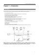
4 & 8 Channel Digital Video Recorder Chapter 1 — Introduction FEATURES Your color digital video recorder (DVR) provides recording capabilities for four or eight camera inputs.
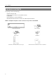
User’s Manual PACKAGE CONTENTS The package contains the following: Digital Video Recorder Power Adaptors and Power Cords (DVR, Camera) USB Mouse Infrared Remote Control and Batteries REVO Remote Pro Software CD and User’s Manual (This document) NOTE: The adaptor and power cord for camera are only for the 8-channel DVR.
4 & 8 Channel Digital Video Recorder Chapter 2 — Installation & Configuration REAR PANEL CONNECTORS No special tools are required to install the DVR. Refer to the installation manuals for the other components that make up part of your system. Your DVR should be completely installed before proceeding.
User’s Manual A VGA connector is provided so that you can use a standard, multi-sync computer monitor as your main monitor. Use the cable supplied with your monitor to connect it to the DVR. The VGA monitor is automatically detected when you connect it. NOTE: The DVR supports simultaneous operation of a CCTV and a VGA monitor. Connecting Audio NOTE: It is the user’s responsibility to determine if local laws and regulations permit recording audio. Connect Audio Out to your amplifier using the RCA jack.
4 & 8 Channel Digital Video Recorder NO (Relay Alarm Output): Connect the device to the COM and NO (Normally Open) connector. NO is a relay output which sinks 1A@30VDC (NO). Connector Pin Outs: Alarm In (1 to 8) GND NO COM Alarm Inputs 1 to 8 Chassis Ground Alarm Out (Normally Open) Common Connecting to the RS-485 Port The RS-485 connector can be used to control PTZ (pan, tilt, zoom) cameras. Connect TX+/RX+ or TX-/RXof the control system to the + or – (respectively) of the DVR.
User’s Manual NOTE: When you use wireless communication devices (such as Wi-Fi or Bluetooth) near the DVR, the remote control might not function properly. HDD LED The HDD LED flickers when the DVR is recording or searching video on the hard disk drive. Power LED The power LED is lit when the unit is On. Alarm LED The Alarm LED is lit when alarm output or internal buzzer is activated. USB Port Connect the supplied USB mouse to one of the ports.
4 & 8 Channel Digital Video Recorder CAMERA Buttons Pressing the individual camera buttons will cause the selected camera to display full screen. Buttons 1 to 9 are also used to enter passwords. SEQUENCE Button When in the Live Monitoring mode, pressing the SEQUENCE button displays live channels sequentially. FREEZE Button Pressing the FREEZE button freezes the current live screen.
User’s Manual ZOOM Button Pressing the ZOOM button zooms the current image on the screen. A PIP with a rectangle temporarily displays showing what area of the screen has been enlarged. You can use the arrow buttons to move the rectangle to another area. PTZ Button Pressing the PTZ button enters the PTZ (Pan/Tilt/Zoom) mode which allows you to control properly configured cameras. Enter Button (Enter) button selects a highlighted item or completes an entry that you have made during system setup.
4 & 8 Channel Digital Video Recorder To enter the setup screen… To select items… To change values… To enter characters… Remote Control In Live Monitoring mode, press the MENU button to display the menu icons at the top (Setup) icon by of the screen. Select the pressing the button. Move to the desired item by pressing the arrow buttons ( ) and select it by pressing the button.
User’s Manual Date/Time Setup Date: Set the system date and select the date format. Time: Set the system time and select the time format. Time Zone: Select your time zone. The Time Zone can be selected on the map. Use Daylight Saving Time: Selecting the box sets the system to use daylight saving time. NOTE: The Date/Time will be set, and the clock will start when you click the Next button.
4 & 8 Channel Digital Video Recorder Select the Next button to start the Network Setup Wizard. NOTE: The Network wizard also can be accessed by selecting Network Setup in the Main Setup screen. Refer to the following Advanced Setup section. Internet Connection Select whether or not your DVR is connected to the Internet. LAN Setup Select between Auto Configuration and Manual Configuration for network configuration, and then select the Test button to test the network configuration you selected.
User’s Manual REVO Dashboard Setup I Select the Next button to start the Dashboard Setup. REVO Dashboard Setup II Select New account if you want to create a new Dashboard account, and select Existing account if you want to use your existing Dashboard account. REVO Dashboard Setup III Enter the User ID and Password for your Dashboard account. And then register the DVR you want to access by entering the DVR name and selecting the Register/Add a new DVR button.
4 & 8 Channel Digital Video Recorder ADVANCED SETUP To enter the Main Setup screen, press the MENU button on the remote control. Select the of the screen by pressing the button. The Login screen appears. (Setup) icon at the top Select a User and enter the password by pressing the appropriate combination of Camera number buttons on the remote control and select the OK button. The factory default password is 1234 for a User and there is no password for an admin user. button for guidance.
User’s Manual System Menu Network Menu Camera Menu Record Menu Event Menu Display Menu NOTE: When the installed hard disk drive is not formatted, a message box appears asking you to format the hard disk drive. If you want to record video, you must format the hard disk drive. SYSTEM SETUP System Settings (SYSTEM System Tab) System ID: Set the system ID. Use the Up and Down arrow buttons or scroll the mouse wheel to increase or decrease the number.
4 & 8 Channel Digital Video Recorder Show System Log…: Displays the system logs (up to 5,000 from the latest). The icon will be displayed in the last column for system activities of remote sites. To export the system log information, connect the USB device to the DVR. Select Export… and press the button, and the System Log Export screen displays. Select the box beside File name and press the button. A virtual keyboard allows you to enter the file name.
User’s Manual Storage Settings (SYSTEM Storage Tab) Capacity: Displays the capacity of the storage drive. Disk Bad: Displays the damage status of the storage drive. Not Formatted – The device is not formatted. Good (%) – Less than user-defined percentage of bad disk sections is damaged. Bad – More than user-defined percentage of bad disk sections is damaged. Temperature: Displays the temperature of the storage drive. N/A – The DVR cannot read the temperature.
4 & 8 Channel Digital Video Recorder Enable SSL for Transferring Data: Selecting the box turns the SSL (Secure Sockets Layer) authentication On. When it is On, the security of data, except video transmitted for remote monitoring or remote recording can be enhanced by using the SSL (Secure Sockets Layer) authentication. When using the SSL function, the DVR cannot be connected with a remote program or a network keyboard which does not support the SSL function.
User’s Manual Port Number Setup…: Set the port number of each remote software related program. NOTE: You will need to get the appropriate Port Numbers for each remote software related program from your network administrator. Do NOT use the same port number for two different programs, otherwise, the DVR cannot be connected with the PC running REVO Remote Pro or REVO Remote. CAUTION: When changing the port settings, you must change the port settings on the PC running REVO Remote Pro.
4 & 8 Channel Digital Video Recorder Dashboard – Setup: Select the button and set up the Dashboard. Select New account if you want to create a new Dashboard account, and select Existing account if you want to use your existing Dashboard account. Enter the User ID and Password for your Dashboard account. And then select the Register/Add a new DVR button to register the DVR on the REVO Dashboard.
User’s Manual Recipient: Enter the recipient’s e-mail address and select the mail server provider. The e-mail address must include the “@” character to be a valid address. : Deletes the mail accounts. SMTP Setup: Select the button and set up the SMTP server. Type – Select between Manual and listed SMTP mail server providers. SMTP Server – Enter the SMTP server IP address or domain name obtained from your system administrator.
4 & 8 Channel Digital Video Recorder Daily Report Setup…: Select the button and set up the daily report of event detection. Checking the Enable box enables the daily report setup. Set the reporting time and time range of daily report and select the cameras for which you want the daily report of events, and the DVR will send an email of daily report based on the reporting condition you made. CAMERA SETUP Camera Settings No.: Selecting the box toggles all or each camera On and Off.
User’s Manual NOTE: When set to High or Very High resolution, the maximum recording speed of each camera channel might decrease so as not to exceed the total ips of all camera channels. The 8-channel DVR has two camera groups (No. 1: cameras 1 to 4 and No. 2: cameras 5 to 8), and setting resolution will be applied to all the cameras within the same camera group. See the table below. No. of cameras set to On and High resolution 0 1 2 3 4 ─ 30 ips 30 ips 20 ips 15 ips No.
4 & 8 Channel Digital Video Recorder Setting up the Advanced Schedule Mode… Schedule Type: Select the Advanced schedule mode. Pre-Event Record: Selecting Setup… allows you to set up the pre-event recording by setting the ips, Quality and Dwell for each selected camera channel. Post-Event Record Dwell: Set the length of time you would like to record for the associated event. Add Schedule…: Adds a schedule item. Up to 20 schedules can be registered. No. – Indicates a schedule number.
User’s Manual No.: Your DVR has built-in motion detection. Selecting the box turns the motion detection On and Off for each camera. Sensitivity: Set the DVR’s sensitivity to motion for Daytime and Nighttime independently from 1 (the least sensitive) to 5 (the most sensitive). Zone: Define the area of the image where you want to detect motion; e.g., a doorway. The Motion Detection Zone screen is laid over the video from the selected camera.
4 & 8 Channel Digital Video Recorder Motion Ignoring Interval: Set the motion ignoring dwell time. You can control excessive event logging and remote notification of motion detected after the motion dwell time by adjusting the motion ignoring dwell intervals. The DVR will not log and notify motion events occurred during the preset interval range. The recording for motion events will not be affected by the Motion Ignoring function. Daytime Setup…: Select the button and set the Daytime range.
User’s Manual Actions: Set up actions the DVR will take whenever it detects system events. System events can sound the DVR’s internal buzzer, notify a number of different devices and/or move PTZ cameras to preset positions. NOTE: The Alarm Out action cannot be set to System, Boot Up, Restart, Shutdown and Panic Record events. NOTE: For the Notify action to work, the Mail should be enabled in the NETWORK – Mail setup. Beep on Video Loss: Set to sound the DVR’s internal buzzer when video is lost.
4 & 8 Channel Digital Video Recorder Main Monitor Settings (DISPLAY Main Monitor Tab) Sequence – Mode: Select the sequence mode between Full Sequence and Cameo Sequence. (8-ch model only) Selecting the Sequence menu icon at the top of the screen or pressing the SEQUENCE button on the remote control causes the DVR to sequence cameras. The DVR can sequence cameras in two modes: “Full” and “Cameo.” In the Full mode, the DVR sequences through the cameras with predefined screen layouts.
User’s Manual 28
4 & 8 Channel Digital Video Recorder Chapter 3 — Operation NOTE: This chapter assumes your DVR has been installed and configured. If it has not, please refer to Chapter 2. LIVE MONITORING As soon as the DVR completes its initialization process, it will begin displaying live video on the attached monitor and playing live audio through the attached speaker. The default mode is to display all cameras at once. Pressing any camera button on the remote control will cause that camera to display full screen.
User’s Manual Camera Menu Selecting the (Camera Menu) icon displays the following Camera Menu. PTZ: Selecting PTZ and choosing the camera number allows you to control the selected camera as long as it has Pan, Tilt and Zoom capabilities. Selecting PTZ is the same as pressing the PTZ button on the remote control. See the following PTZ Mode section for details. Zoom: Selecting Zoom and choosing the camera number zooms the current image of the selected camera on the screen.
4 & 8 Channel Digital Video Recorder Login/Logout Selecting (Login) in the Live Monitoring menu accesses the Login screen, and you will be asked to enter the password to log into the system. Selecting (Logout) in the Live Monitoring menu displays the Logout screen asking you to confirm whether or not you want to log out the current user. DISPLAY MENU In the Live Monitoring mode or Search mode, moving the mouse pointer to the left edge of the screen displays the following Display menu icons.
User’s Manual EVENT MONITORING When an event occurs, the DVR will display the camera associated with that event if Event Monitoring On is selected in the Display setup screen (OSD tab). How the cameras are displayed depends on the number of cameras associated with the event. If one camera is associated with the event, the DVR will display that camera full screen. If two to four cameras are associated with the event, the DVR will display the cameras on a 2x2 screen.
4 & 8 Channel Digital Video Recorder While in the PTZ mode, pressing the MENU button on the remote control displays the menu icons at (Advanced PTZ) icon displays the following the PTZ menu. the top of the screen. Selecting the Set the feature you wish to control by selecting it from the menu. Refer to the camera’s instructions for the proper settings. Depending on the camera specifications, some features may not be supported. You also can use the mouse for convenient PTZ control.
User’s Manual PLAYING RECORDED VIDEO While in the Live Monitoring, pressing the MENU button on the remote control displays the menu icons on the screen. (Search Mode) icon at the top of the screen exits the Live Monitoring mode and enters the Search mode. Selecting the (Play/Pause) button on the remote control in the Once video has been recorded, you can view it by pressing the Search mode. When playing video for the first time, the DVR will display the most recent image.
4 & 8 Channel Digital Video Recorder Search Go To Export Camera Menu Alarm Panic Exit NOTE: The menu icons also can be displayed by moving the mouse pointer to the top of the screen. Search: Selects video from the event log, searches using a recording table or searches motion events (see below for more details). Go To: Displays the first or last recorded image, or searches by date and time (see below for more details). Export: Copies a video segment and saves it (see below for more details).
User’s Manual Panic: Starts panic recording of all cameras. Selecting the PANIC button on the remote control. again stops panic recording. It is the same as pressing Exit: Exits the Search mode and enters the Live Monitoring mode. SEARCH Event Log Search The DVR maintains a log of each time the Alarm Input port is activated. The Event Log Search screen displays this list. Use the arrow buttons to highlight the event for which you would like to see video.
4 & 8 Channel Digital Video Recorder Once you set your desired search conditions, select Search and press the button to display the search results in the Event Log Search screen. Selecting Cancel exits the screen without saving the changes. Record Table Search Standard View Compact View Expanded View Recording information about video images currently displayed on the screen displays in the recording status bar. A grey vertical line indicates the current search position.
User’s Manual Go To: Displays the first or last recorded image, or searches by date and time (see below for more details). Backup: Copies a video segment and saves it (see below for more details). Zoom: Zooms the current playback image. Enable De-Interlace: Turns the de-interlace filter on. Slow Play: Plays video at low speed (x1/2, x1/3, x1/4, x1/6 and x1/8). NOTE: Playing video at low speed will be supported for video recorded 10 images or more per second.
4 & 8 Channel Digital Video Recorder GO TO Go to the First Selecting Go to the First displays the first recorded image. Go to the Last Selecting Go to the Last displays the last recorded image. Go to the Date/Time You can use the Left and Right arrow buttons on the remote control to select the year, month, day, hours, minutes and seconds. Use the Up and Down arrow buttons to change to the date and time you want to search for video. Once you have set the date and time, press the button.
User’s Manual From: Pressing the button toggles between On and Off. When set to Off, you can enter a specific Date and Time. When set to On, the copy will be from the first recorded image. button toggles between On and Off. When set to To: Pressing the Off, you can enter a specific Date and Time. When set to On, the copy will be to the last recorded image. Channels: Select the cameras that you would like to include in your video clip.
4 & 8 Channel Digital Video Recorder Start Internet Explorer on your local PC. You can run the REVO Remote program by entering the following information in the address field. – “http://IP address:port number” (The DVR IP address and the REVO Remote port number (default: 12088) set in the Network setup screen (General tab)) – Or, “http://www.revodvr.
User’s Manual ① Click the icon to log out of the REVO Remote program ② Click the icon to access the web search mode. ③ Position the mouse pointer on the Remote Watch logo to see the version number of the REVO Remote program. ④ The DVR information window displays the login information of REVO Remote. ⑤ Click the screen format to select the desired display mode. When changing the screen format, the selected camera on the current screen will be located in the first cell of the new layout.
4 & 8 Channel Digital Video Recorder NOTE: The icon will display on each camera screen when audio communication is available between the REVO Remote system and a DVR. WEB SEARCH Remote Search is a remote web search program that allows you to search recorded video on the remote DVR. NOTE: The remote site connection in the Web Search mode will automatically be disconnected if there is no activity for 30 minutes. ① Click the icon to log out of the REVO Remote program.
User’s Manual NOTE: When saving as an executable file, selecting the Exclude Player option will reduce the file size and its saving time. You can download the Player program to review the video clip by entering the following information in the address filed of Internet Explorer. – When using the DVRNS: “http://www.revodvr.com/DVR Name/REVOBackup.exe” (The DVR name registered on the DVRNS server) – When not using the DVRNS: “http://IP address:port number/REVOBackup.
4 & 8 Channel Digital Video Recorder Appendix ERROR CODE NOTICES SYSTEM UPGRADE RELATED BACKUP RELATED No. Description No. 0 1 2 3 4 100 101 102 103 104 105 300 301 302 303 304 400 401 402 500 Unknown error. File version error. Operating system version error. Software version error. Kernel version error. Upgrade device mounting failed. Package is not found. Extracting package failed. LILO failed. Rebooting failed. Invalid package. Remote connection failed. Remote network error.
User’s Manual MAP OF SCREENS (ADVANCED SETUP) 46
4 & 8 Channel Digital Video Recorder SPECIFICATIONS VIDEO Signal Format Video Input Playback/Record Speed (images per second) NTSC 4 or 8 RJ-12 inputs, 1 Vp-p, auto-terminating, 75 Ohms Composite: One (RCA), 1 Vp-p, 75 Ohms VGA: One Composite: 720x480 VGA: 800x600@60Hz, 1024x768@60Hz, 1280x1024@60Hz 8-ch Model 240/240ips (NTSC) 4-ch Model 120/120ips (NTSC) Alarm Input Alarm Output Internal Buzzer Network Connectivity Audio Input Audio Output IR Port 4 or 8 TTL, NC/NO programmable, 4.3V (NC) or 0.
User’s Manual 48
4 & 8 Channel Digital Video Recorder Index A Active Cameo Mode ................................................ 32 ADSL ....................................................................... 18 Advanced Schedule Mode ...................................... 23 Advanced Setup ...................................................... 13 Alarm ....................................................................... 30 Alarm Button ............................................................. 9 Alarm Out ..........
User’s Manual N NAT ......................................................................... 18 NC (Normally Closed) ............................................. 25 Network Setup......................................................... 17 Nighttime ................................................................. 24 NO (Normally Open) ........................................... 5, 25 Notify ....................................................................... 25 O OSD Margin............................