REVOLABS EXECUTIVE HD™ Wireless Microphone System Models: 01-HDEXEC, 01-HDEXEC4, 03-HDEXECEU and 03-HDEXEC4EU Installation and Operation Guide
© 2009 REVOLABS, INC. All rights reserved. No part of this document may be reproduced in any form or by any means without express written permission from Revolabs, Inc. Product specifications are subject to change without notice. Revolabs Executive HD™ Manual 01-HDEXECMAN-PAP-11 May 2009 (Rev 1.
Contents Safety and General Information .................................................................................................................... 1 Introduction.................................................................................................................................................... 3 System Components ................................................................................................................................
Safety and General Information Please read the following information to ensure safe and efficient use of your Revolabs system. FCC User Information FCC Registration Number: 0014898290 FCC ID: T5V01HDEXEC Revolabs Executive HD™ Base Station FCC ID: T5V01HDEXEMIC Revolabs Executive HD ™ Microphone FCC Notice to Users Users are not permitted to make changes or modify the equipment in any way. Changes or modifications not expressly approved by Revolabs, Inc.
Export Law Assurances This product is controlled under the export regulations of the United States of America and Canada. The Governments of the United States of America and Canada may restrict the exportation or re-exportation of this product to certain destinations. For further information contact the U.S. Department of Commerce or the Canadian Department of Foreign Affairs and International Trade. The use of wireless devices and their accessories may be prohibited or restricted in certain areas.
Introduction Congratulations on your purchase of a Revolabs digital wireless microphone system! This system utilizes 1.9 GHz DECT technology, and high band-width audio from multiple wireless microphones, enabling clear, reliable, un-tethered communications in recording, audio/video conferencing, speech recognition, VOIP communications, sound reenforcement as well as many other environments requiring clear audio capture.
Mixing Acoustic echo cancellation (AEC) Feedback elimination Level control Equalization Noise cancellation The system is designed to optimize audio capture/reproduction by providing: Consistent audio input from all participants Minimum room noise Mute control Wireless encryption Automatic channel selection Full duplex audio. The Charger Base stores and charges the wireless microphones when not in use.
Controls and Connections: 1. Channel LED indicators: Displays microphone mute and pairing states. 2. Diversity Antenna: One or two sets (4 channel or 8 channel). 3. Pairing Push Buttons: For pairing microphones to Base Station. 4. Two Line LCD Display for front panel operation, command and control. 5. Navigation Buttons for menus on front panel LCD interface. (see Section Using the Base Station Front Panel Display ) 6. On/Off Switch: Powers up unit. 7. Power In Receptacle (100-240 VAC). 8. Ethernet Port 9.
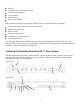
Revolabs Executive HD™ Audio Connections There are (8) 3.5mm mini-Phoenix inputs and (8) 3.5mm mini-Phoenix outputs on the back panel of the unit (four on the 4-channel system) providing access to each channel‘s audio signal. The provided mini-Phoenix connectors are designed for easy wiring. The three terminals (from left to right) correspond to positive +, negative -, and shielded ground . To connect audio In/Out on the Base Station 1. Use the screws on top of the connector to first loosen the terminals.
The three terminals of the BUS connector should be wired in parallel (seen left to right with the connector installed). The three contacts of the phoenix connector are as follows from left to right. 1. Sync 2. Master Mute 3. Ground Set one Base Station as the Primary device by putting DIP switch #1 to the ‗Off‘ position. The other units must be set as Secondary devices by putting DIP switch #1 to the ‗On‘ position.
Using the Rear Panel Configuration DIP Switches off on 12345678 1 – Operation Mode - Primary (off)/Secondary (on) Used when connecting several base stations together for operation in the same area. One system must be set to ‗Primary‘, and all others must be set to ‗Secondary‘. 2 - future use 3 - future use 4 – Audio Output Level - Line (off)/Mic (on) This controls the output audio level on all audio output connectors.
Scan Network The ‗Scan Network‘ option of the ‗Box‘ menu will search the connected Ethernet network for all connected HD Base Stations. A pop-up ‗Equipment List‘ will show all discovered devices and allow the connection to the selected Base Station(s). Once connected to a Base Station, the HD Control Panel will open a device tab for each Base Station. Note: If the „Equipment List‟ does not appear after a network scan has been performed, no devices or network connections were found.
Set Telnet Password A Telnet Password may be assigned for logging into a Base Station. Once a Telnet Password is assigned, it must be entered to communicate with the Base Station over Ethernet. The Telnet Password can be set by selecting ‘Set Password’ from the ‘Box’ menu. The corresponding pop-up will show if a password has been set and will allow the password to be changed. Set IP Configuration Executive HD Base Stations are set by default to look for a DHCP server when an Ethernet connection is present.
Update Firmware Executive HD Systems are field upgradable for the firmware portion of the Base Station and Microphones. The firmware must be sent to the Base station and Microphones separately using the HD Control Panel program. (See Updating the Revolabs HD Firmware for more information) Serial Control Processor The Serial Control Processor allows the use of third party control system or DSP to monitor and control the Executive HD Base Station and Microphones.
Transmit Power The transmit power of the Base Station can be adjusted to help reduce the operational radius of a Executive HD System in order to prevent interference from other Revolabs Products, or from other devices operating in the same frequency. The options for transmit power are ‗0-7‘ with ‗0‘ representing the lowest power and ‗7‘ representing the highest power. This configuration setting can also be controlled using the Base Station front panel display.
Microphone Type This provides the current type for the microphone that is active on each channel. Microphone Status This provides the current status for the microphone paired to each channel. Microphone Version This provides the current firmware version for the microphone that is active on each channel. Microphone Battery This provides the current battery level for the microphone that is active on each channel. Versions This window provides all the current firmware versions found in the Base Station.
When using a control system, the microphone mutes can be configured to ―int. mute‖ (default), which mutes the microphone audio inside of the base station, or ―ext. mute‖, which allows the control system to choose another location for the mute to take place. Note: Both a control system and DSP cannot be connected to a Base Station at the same time. When using a control system, the DSP control must be done by the control system and not the Base Station.
Channel #: The options for the portion of the serial strings are ―1-8‖ since each Base station can only control up to 8 channels of an Executive HD microphone system. The corresponds to the physical channel that the microphone is paired to on the front of each Base Station. A of ―A‖ will enable or disable the Master Mute mode. This command must only be sent to the Base Station that is set to ―Local‖. ―Remote‖ Base Stations will not accept the command.
Biamp Audia & Nexia When using the Base Station along with a Biamp DSP, you must select the corresponding DSP product line from the ―Serial Control Processor‖ menu in the Revolabs HD Control Panel software. You must also set the RS-232 or Network settings of the Base Station to match the communication settings of the Biamp DSP as well as select the ‗Audio Channels‘ of the microphones that the Base Station is to simulate.(i.e. 1-8, 9-16, etc.
So for example, if you set the ‗Audio channels‘ for the microphones to 1-8, in the Control Panel, then the Base Station will use the instance ID tag of ―MUTE1‖, and control the first 8 mutes in that fader block. Note: Instance ID tags are case sensitive and must be entered correctly in order to function properly. A “level block” must be used as the method of muting.
Each Base station will control the mutes of each individual microphone channel, within the DSP programming, using that channels name.
The following is a list of the configuration settings that can be changed using the front panel display controls. 1. Select High Definition or Max Density modes 2. Select the operation range of the Base Station 3. Select the microphone mute mode Note: Switching between High Definition and Max Density modes will cause the Base Station to automatically reboot.
Revolabs HD Wearable Microphones turn on and mute automatically when removed from Charger Base, to reduce noise while being attached. To use the HD Wearable Microphone: 1. Remove the microphone from the Charger Base. 2. Attach the microphone to clothing or to a lanyard, position microphone just above the sternum or breastbone, within 6 - 12 inches (15 – 30cm) from the mouth is recommended. Make sure microphone is attached securely with the microphone port pointed up toward mouth. 3.
360 º pickup pattern 1 2 3 6 5 4 Using the HD Omni-Directional Tabletop Wireless Boundary Microphones The HD Omni-directional TableTop Wireless Boundary Microphones enable multiple conference attendees to use a single microphone. 1. 2. 3. 4. 5. 6. LED display — visual status for mute, un-mute, and pairing. Mute button — press to mute, un-mute and pair microphone. Audio jack — accepts a 2.5mm plug. Charging port — docks to Solo Charger Bases. Rubber feet — non-slip, vibration absorbing pads.
4. To turn microphone off, return the microphone unit to the Charger Base or press and hold the Mute button for ~10 seconds until the LED turns solid RED and release button. If the microphones are placed too far from the Base Station (~100 feet or 30 meters) the connection will be dropped (LED flashes all colors) and the microphone will mute. After 15 seconds the microphone will beep 5 times, and will continue beeping every 30 seconds to indicating it‘s out of range.
3. With the microphone in position, un-mute the microphone by pressing and releasing the Mute button (confirm by a flashing GREEN LED). 4. To turn microphone off, return the microphone unit to the Charger Base or press and hold the Mute button for ~10 seconds until the LED turns solid RED and release button. If the microphones are placed too far from the Base Station (~100 feet or 30 meters) the connection will be dropped (LED flashes all colors) and the microphone will mute.
To use the HD Universal Wireless Adapter: 1. Remove the Microphone Adapter from the Charger Base. The adapter turns on and mutes automatically when removed from Charger Base (flashing RED LED). The XLR Microphone Adapter is attached to a standard dynamic microphone to convert it from a wired microphone to a wireless microphone (see following figure). The Adapter does not provide phantom power or bias current so it cannot be used with condenser or electret microphones. 2.
When channels are paired, both microphone and channel LEDs will flash RED as microphones are removed from the Charger Base and flash GREEN when un-muted. Remember that only one microphone can be paired to any single Base Station channel. To pair the microphone to the Base Station: 1. Turn the microphone OFF (no LED activity). If the microphone is ON, press and hold the Mute button for 10 seconds until the LED turns solid RED then release the button to turn the unit off.
Power Module The Charger Base requires 9-24VDC power, provided by the AC Adapter. Plug the supplied AC adapter into an appropriate power outlet 110-240 AC, 50-60Hz. The power LED on the Charger Base will illuminate. Charging the Microphone Batteries First-time use — Before using the wireless microphone the first time, charge the batteries in the microphones for eight hours (or overnight) in the Charger Base.
1. Connect to the Base Station(s) as described in Using the Revolabs HD Control Panel Software Interface. 2. Select ‗Update Firmware‘ in the firmware menu. 3. Select the desired firmware version from the menu in the pop-up window. 4. Select the Base Station(s) that you would like to update. 5. Select OK and watch the firmware process either on the Base Station front panel display or in the ‗monitor‘ tab in the Revolabs HD Control Panel program.
Revolabs Executive HD ™ Indicator LEDs The following tables show activities associated with the various states shown by the LEDs: Equipment Use Microphone LED Microphone in Charger Base Microphone not in Charger Base Solid RED Solid GREEN OFF Base Station Channel LEDs OFF OFF OFF Two RED flashes every 1.5 seconds GREEN flash every 1.5 seconds Solid RED Two RED flashes every 1.5 seconds GREEN flash every 1.
Warranty Revolabs, Inc. warrants this product to be free of manufacturing defects. Repair or replacement of any defective part or unit (at the discretion of the Seller) will be free of charge for the period of one year. Any attempt by the user to alter the equipment, or equipment damaged by negligence, accident, or Acts of God voids this warranty. The Seller shall not be liable for any consequential damage resulting from the malfunction of this product.
Specifications Dimensions, (L, W, H) and Weight: Executive Base Station 16.9‖ (43.03 cm) x 8.0‖ (20.32 cm) x 1.7‖ (4.42 cm), 6.5 lbs (2.95 kg) Charger Base 8.3‖ (21.1 cm) x 4.3‖ (10.9 cm) x 1.0‖ (2.56 cm), 1.0 lb (0.45 kg) Wireless Microphones Wearable: 0.9‖ (2.3 cm) x 0.8‖ (2.0 cm) x 2.6‖ (6.6 cm), 0.05 lb (0.02 kg) TableTop: 1.5‖ (3.8 cm) x 0.8‖ (2.0 cm) x 3.3‖ (8.4 cm), 0.05 lb (0.02 kg) XLR Adapter: 0.9‖ (2.3 cm) x 0.8‖ (2.0 cm) x 4.0‖ (10.2 cm), 0.05 lb (0.02 kg) Shipping Weight 12.0 lbs (5.
Security: 128-bit DSAA (DECT Standard Authentication Algorithm) authentication, 64 bit DECT Standard Cipher Included Accessories: 1 Earpiece with inline volume control and 1 Lanyard per Wearable Microphone Environmental Requirements: Temperature Humidity 40° to 105° F (5° to 40° C) operating 20% to 85% Index . Mini-Phoenix Connectors, 5 .
Note: Microphones must be fully charged and paired to the Charger Base prior to first use. Revolabs Executive HD ™ Manual 01-EXEMAN-PAP-11 May 2009 (Rev 1.