Revolabs Fusion™ Wireless Microphone System Set-Up Guide Microphones must be fully charged and paired to the Fusion Base Station prior to first use. © 2008 REVOLABS, INC. All rights reserved. No part of this document may be reproduced in any form or by any means without express written permission from Revolabs, Inc. Product specifications are subject to change without notice. Part #295034 REV 1.12 Rev 1.
Table of Contents Revolabs Fusion™ Contents of Box 4 Details About the Fusion 5 Fusion Front Panel 5 Fusion Back Panel 6 Fusion Set-Up 7 Audio-Conferencing 8 Video-conferencing Configuration 8 Pairing Microphones to Fusion Base Station 9 Configuring Fusion with Video-conferencing Stations 11 Polycom Installation 12 Tandberg Installation 14 Lifesize Installation 15 Sony Installation 16 Warranty Revolabs, Inc. warrants this product to be free of manufacturing defects.
Set-Up Guide Revolabs Fusion™ Specifications Dimensions, (L, W, H) and Weight: Fusion Base Station 16.45 x 8.46 x 1.7”, 8.7 lbs 41.8 x 21.5 x 8.7 cm, 3.95 kg Charger Base 8.3 x 4.3 x 1.0”, 1.0 lb 21.2 x 10.9 x 2.56 cm, 0.45 kg Wireless Microphones Wearable: 0.9 x 0.8 x 2.6”, 0.05 lb 2.3 x 2.0 x 6.6 cm, 0.02 kg Tabletop: 1.5 x 0.8 x 3.3”, 0.05 lb 3.8 x 2.0 x 8.4 cm, 0.02 kg XLR Adapter: 0.9 x 0.8 x 4.0, 0.05 lb 2.3 x 2.9 x 102 cm, 0.02 kg Radio Frequency: 01-8FUSION-NM-01-01 1.92 to 1.
Set-Up Guide Revolabs Fusion™ EUROPEAN COMPLIANCE This equipment has been approved in accordance with Council Directive 1999/5/EC “Radio Equipment and telecommunications Equipment. Contents of box: Fusion Base Station and four or eight wireless microphones (any type) Conformity of the Equipment with the guidelines below is attested by the CE mark.
Set-Up Guide INDUSTRY CANADA NOTICE TO USERS Operation is subject to the following two conditions: (1) This device may not cause interference and (2) This device must accept any interference, including interference that may cause undesired operation of the device.
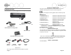
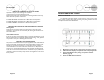
Set-Up Guide Revolabs Fusion™ Fusion Back Panel 1. 2. Power 6 RCA Plugs • AUX IN (for auxiliary input devices) • • • • • 3. 4. 5. 6. 7. 8. 9. 10. 11. NOTE: This equipment has been tested and found to comply with the limits for a Class B digital device, pursuant to part 15 of the FCC Rules. These limits are designed to provide reasonable protection against harmful interference in a residential installation.
Set-Up Guide Safety and Regulatory Information Please read the following information to ensure safe use of your Revolabs system. FCC User Information FCC Registration Number: 0014898290 FCC ID: T5V2FUSION 8 Revolabs Fusion™ Base Station 8 microphones FCC ID: T5V2FUSION4 Revolabs Fusion™ Base Station 4 microphones FCC ID: T5V-01-EXEMIC Revolabs Solo™ Executive Microphone FCC NOTICE TO USERS Users are not permitted to make changes or modify the equipment in any way.
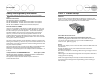
Set-Up Guide STEP 2: Audio Conferencing Plug Cable A (single RCA to double RCA) single RCA connector into Fusion Base Station RCA port, and then plug the double RCA connectors into the powered speakers or a powered amplifier. Plug speakers into wall outlet. Plug one end of Cable B, the phone line cable, into the Fusion Base Station , plug other end into phone jack. You may also plug a phone into the RJ11 , You may then dial with the remote control or the phone.
Set-Up Guide Revolabs Fusion™ Indicator Lights Equipment Use Microphone LED Microphone in Charger Base Solid RED Solid GREEN Microphone not in Charger Base OFF One RED flash every 1.5 seconds Two RED flashes every 1.5 seconds GREEN flash every 1.
Revolabs Fusion™ Set-Up Guide STEP 3 Continued: Pairing Microphones to Fusion Base Station if Necessary Hearing Assistance Setting the Hearing Assistance Option All Microphones Hear Audio From the Far End (default) Place the microphone unit into pairing mode by holding the MUTE button down for seven seconds. The LED will turn solid RED. Release the MUTE button. The microphone is now in pairing mode.
Set-Up Guide Remote IR Sensor Setting the Remote IR Sensor Option Revolabs Fusion™ Configuring the Fusion with the Video Conferencing System Front Panel IR Sensor (default) If the Fusion Base Station is within view of the Remote Control, the front panel IR Sensor will accept all Remote Control functions. DIP switch #7 is OFF (page 18). The following pages have a representative sample of the most popular videoconferencing systems.
Set-Up Guide Revolabs Fusion™ Polycom® Installation (Polycom VSX7000 shown for example) This information is meant to be illustrative only. Consult your Polycom Videoconferencing System Administrator Manual for specific instructions. Phone Auto Answer Setting Phone Answering Mode Answer with Remote Control (default) To answer a phone call and begin a teleconference, the user must use the Remote Control and press the “Call” key. DIP switch #6 is OFF (page 18).
Set-Up Guide Tabletop Master Mute Setting the Mute Option Individual Muting (default) In the default setting, each Solo microphone will mute only itself when its mute button on the microphone is pressed. To mute all of the microphones, press the red MUTE button on the Remote Control; all microphones will flash red and no individual microphone can be unmuted until the remote MUTE button is pressed again. All microphones will return to their prior state. DIP switch #5 is OFF (page 18).
Revolabs Fusion™ Set-Up Guide Tandberg™ Installation (Tandberg Edge 95 shown for example) This information is meant to be illustrative only. Consult your Tandberg Videoconferencing System Administrator Manual for the specific instructions. Multiple Fusion Systems There are two settings that must be adjusted when more than one Fusion system is used within a 100’ (30.5 m) range: frequency and transmit power level.
Set-Up Guide Revolabs Fusion™ Programming Port: DIP Switches Tandberg™ Installation (Tandberg Profile MXP shown for example) The Fusion Base Station factory default settings are all OFF. The left Programming Port (#8, page 6) is end-user configurable. Programming Port (#9, page 6) on the right is reserved for Revolabs Use Only. This information is meant to be illustrative only. Consult your Tandberg Videoconferencing System Administrator Manual for the specific instructions.
Set-Up Guide Revolabs Fusion™ Lifesize® Installation (Lifesize Team shown for example) Sony® Installation (Sony G70 shown for example) This information is meant to be illustrative only. Consult your Lifesize Videoconferencing System Administrator Manual for specific instructions. This information is meant to be illustrative only. Consult your Sony Videoconferencing System Administrator Manual for the specific instructions. NOTE: Requires special adapter cable - XLR Female to 3.5 mm mini connector.