Bump Controller User’s Guide Firmware v4.05 and later © 2015, 2016, 2017 FMA,Inc.
Contents Contents............................................................................................................. 2 About BUMP Technology .................................................................................................... 3 About the BUMP Controller ................................................................................................. 4 Cabling and Installation.......................................................................................................
About BUMP Technology BUMP is an exclusive Revolectrix concept for Battery Management. BUMP technology utilizes Near Field Communication (NFC) technology to communicate with any battery equipped with a BUMP Compliant Tag, or “BumpTag”. BumpTags are pre-installed and pre-configured on most Revolectrix batteries, but are also available separately, so customers can configure them for use with any battery of their choice.
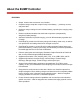
About the BUMP Controller FEATURES: • Simple, intuitive color touchscreen user interface • Complete charger setup with a simple "bump" of the battery ...
HARDWARE CAPABILITIES: • High-brightness, 2.8" QVGA TFT LCD with resistive touchscreen • Integrated BUMP wireless interface for configuring and reading BumpTags on batteries • Integrated Bluetooth 4.
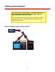
Cabling and Installation CAUTION: ALWAYS INTERCONNECT THE BUMP CONTROLLER AND POWERLAB POWER CONNECTIONS FIRST, BEFORE APPLYING POWER TO ANY OF THEM Failure to comply with the above may result in damage to the Bump Controller and/or the connected PowerLabs which would not be covered under warranty.
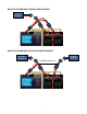
MULTIPLE POWERLABS, SINGLE POWER SOURCE POWER SOURCE MULTIPLE POWERLABS, MULTIPLE POWER SOURCES POWER SOURCE 2 POWER SOURCE 1 COMMON GROUND 7
• • • • • The BUMP Controller must always have a common power ground (negative) connection to all connected PowerLab Battery Workstations. If the common ground connection between BUMP Controller and PowerLabs does not exist at the instant when the positive power wire is connected, excessive current may flow through the PowerLab port(s) and damage the BUMP Controller and/or PowerLab(s).
Configuring CellPro PowerLabs for BUMP Control The Bump Controller is designed to control legacy CellPro PowerLab series chargers (PowerLab6, PowerLab8v2, and Dual PowerLab8x2) via the 3-wire data port interface. The Bump Controller has four (4) data ports available for external chargers.
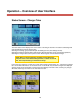
Operation – Overview of User Interface Status Screen - Charger Tabs The main Status Screen displays the current status of all charger channels. The tab text and background color will indicate the current charger state. Selecting the Settings (gear) button will open the Settings screen (see Settings section). Selecting the Manual operation button will open the Manual Operation screen (see Manual Operation). Selecting the charger tabs at the top of the screen will change the current selected charger.
Status Screen - Primary Information NOTE: Manual Rate Controls enable on-the-fly adjustment of the current charge or discharge rate, but the maximum rates are still limited to the max values of the attached pack(s) for safety. Status Screen – Secondary Information Tabs The Information tabs are located near the center of the Status Screen and can be touched to change the information displayed on the lower half of the Status screen.
Pack The Pack tab shows other state information which varies depending on the current charger state. This view is helpful to understand why the charger might be limiting power or performing in any way other than expected. For example, if the maximum power supply amps limit is reached during a charge, or when the maximum internal discharge watts is reached during a discharge. Cell Volts The Cell Volts tab displays the current measured cell voltages.
Cell IR The Cell Internal Resistance tab displays the current measured IR values in milliohms. This information is only available when the charger is charging and balance lead is connected. Cells with significantly higher IR than average or rated values will be highlighted in red or yellow. Figure 2 - Cell Internal Resistance (IR) Supply The Supply tab displays the voltage, amperage, and wattage being supplied to the selected charger.
Temp The Temp tab displays the reported internal temperature of the current selected charger. Figure 3 - Temperature Readings Setup The Setup tab shows the actual configured values that have been sent to the charger to perform the requested operation. This is essentially the details of a “dynamic preset” which is calculated from the BumpTag(s), Battery Preset, or Manual Operation parameters which were used to setup the operation.
Operation – Charger Setup The Bump Controller and PowerLab Touch chargers support several methods of charger setup for battery management. The best method is installing and configuring BumpTags for each battery pack, but that might not always be feasible or desirable. The table below gives a comparison of setup methods and should help to determine when it makes sense to use each.
Operation – Using BumpTags Starting a battery operation using BumpTags is as simple as: 1. 2. 3. 4. 5. Select the charger you want to use by touching the corresponding charger tab Bump the battery on the “BUMP Zone” of the charger Press the operation button at the bottom of the display to change to the desired operation, if needed Connect the battery Press ‘Go’ When you bump a BumpTag, all of the battery ratings and settings are read by the charger and the following Battery Details screen is displayed.
NOTE: The charge counter value on the BumpTag isn’t actually incremented when it is bumped. Once the 10% capacity threshold is reached, the unique ID of that battery (or batteries) is cached to ensure the charge counter gets properly incremented on the next bump. This method works properly even when the battery is charged on multiple chargers. When you remove the BumpTag from the Bump Zone, the battery details screen closes and the idle Status screen will now display the current charger setup.
• Details – opens the battery details screen to show more information and operations Pressing the ‘Go’ button will start the selected operation using the current setup. Pressing the operation select button will pop-up an operation list where you can select a different charger operation. Figure 7 - Select Operation Popup Monitor Pressing the Monitor button will toggle the Monitor operation on and off.
Storage Charge The Storage Charge operation will take the battery pack to the hard-coded storage voltage based on its chemistry. The Normal Charge or Discharge settings in the BUMPTag will be used to perform the storage charge, depending on the level of charge in the battery. NOTE: Constant Voltage mode is enabled on Storage, so the charge/discharge currents will decrease slowly as it approaches the target storage voltage.
Operation – Using Battery Presets Battery Presets are used to store battery management details for a specific type of battery. The settings and parameters for a Battery Preset are nearly identical to those of a BumpTag, but of course a BumpTag is intended to identify a specific battery, not just a type of battery. Since a Battery Preset does not identify a specific battery pack, Battery History data is not cached and uploaded to the CCS app – only BumpTags allow you to track battery history.
Operation – Using Manual Operation The Manual Operation feature allows you to perform operations on batteries without the use of a BumpTag or a pre-configured Battery Preset. The Manual mode has a more limited feature set than BumpTag operation and is not intended to be used as the primary method of charging. The Manual operation button is available on the main charger status screen whenever the charger is idle and no BumpTag or Battery Preset setup has been performed.
Settings The Settings menu allows you to change preferences for the charger itself. The Settings menu is accessed by pressing the Settings button (gear icon) which is visible any time an idle charger is selected.
Settings – Power Supplies To ensure that your chargers do not overload or damage your DC power supply, power supply profiles must be configured to match the power output capabilities of your power supply (or supplies if you have multiple). Upon first use (or after a Factory Restore which clears all settings), you will be prompted to configure power supply settings before proceeding. At this point, select the Settings icon (gear) and walk thru the setup for your power supply.
Basic Setup: Single Power Supply for all connected PowerLabs The most basic, and most common, configuration is where a single DC switching power supply is used to power all chargers in the setup. The following steps will get your PowerLab Touch or Bump Controller up and running quickly for this configuration: 1. In Settings, select Power Supply, and confirm that each charger port is associated to the first power supply profile, named “Supply 1” (default). 2.
Settings – Feature Controls The Feature Controls allow certain software and user interface features to be selectively enabled/disabled or customized to better fit a particular use-case. For example, if the charger is being used with the Revolectrix Mobile CCS app for the purpose of tracking battery history, then “Upload Battery History” should be enabled.
BumpTag Installation BumpTags are small enough and light enough to offer a great deal of flexibility in installation. This section provides some guidelines for attaching the BumpTags to your batteries and some alternative approaches for situations where direct attachment may not be feasible or desirable. 1.
BumpTag Configuration BumpTags contain a wide range of information about your battery.
• Packs: number of separately-charged packs in this battery (default is 1, change for Multi-Packs) BumpTag Ratings Example: Pulse 3700 LiPo 4S 25C Cells: 4S Brand Name: Pulse Pack C-Rating: 25C Capacity: 3700 Chemistry: LiPo Charge Rate Max: 5C (on back label) 28
Factory Ratings Screenshots Multi-Pack Batteries The Pack Count field in Factory Ratings is used to specify that a battery consists of separate packs which have their own mains power leads and can be charged separately. The most common use-case is for large-scale models that use 12S to 16S packs, but a battery can be configured as multi-pack for any cell count, as long as it has an equal number of cells in each pack.
When the Cell Count exceeds 8 (the maximum that can be charged on PowerLab chargers), then the Pack Count count is automatically incremented to 2. This is done to discourage (but not totally prevent) creating a BumpTag which couldn’t be charged with existing chargers. NOTE: Multi-pack batteries can also be setup with separate BumpTags, each one as a single pack, each bumped and started separately.
BumpTag User Settings Unlike BumpTag Factory Ratings, the BumpTag User Settings fields can be changed as often as you like, however you cannot specify any values which would exceed or violate any of the Factory Ratings values. BumpTag User Setttings contain the following fields: • • • • • • • • • • • • • • • • • • Accurate Charge Rate: (default is lesser of 1.0C or 33% of Rated Max Charge C) Normal Charge Rate: (default is lesser of 2.
NOTE: For NiCD or NiMH batteries, the preferences for termination voltages for any of the charging operations are configured as Fallback Voltages, not maximum cell voltages. BumpTag Analysis Data Analysis Data is measured by the charger during Analyze Cycle operations. Analysis Data is not typically edited directly by the user, but is used for analysis, reporting, and historical purposes.
Copying BumpTags The BumpTag Copy operation will let you make an exact copy of another BumpTag (except for the unique ID and charge counter fields). The Copy command can be used for 2 different purposes: 1. Programming a new BumpTag using Copy If the target BumpTag is new (un-programmed), then the entire contents of the source BumpTag (both Ratings and Settings) will be programmed into the new BumpTag. Use this to quickly setup new batteries which are identical to some you already have. 2.
Upgrading Firmware PowerLab Touch and Bump Controller firmware updates can be downloaded over the USB or Bluetooth interfaces, depending on the application used. The PC Firmware Update Utility is strictly for firmware upgrades over USB. The Mobile CCS App includes full control of PowerLab Touch chargers and Bump Controllers over a wireless Bluetooth 4.x Low Energy link, including firmware upgrades.
Revolectrix CCS Mobile App The Revolectrix Charge Control Software (CCS) Mobile App provides complete control over the PowerLab Touch and Bump Controller products using a Bluetooth 4.x Low Energy wireless link. The CCS App also includes automatic firmware upgrades with the latest firmware versions of all supported products bundled with each release of the CCS App. The Android version of the CCS can be purchased and downloaded from Google Play: https://play.google.com/store/apps/details?id=com.revolectrix.
• • • • • • • History, reporting, graphing of battery charge graphs Battery historical performance trending charts (Capacity History and Cell IR History) Quick BumpTag setup (faster data input) Quick Manual operation setup (faster data input) Replace BumpTag Wizard (migrates history data from old BumpTag to new) Remote BumpTag scanning from Android mobile device (NFC support required on mobile device) DropBox integration for backup and sync of battery history data across multiple mobile devices Enabling B
Troubleshooting SYMPTOM: ‘Lost Data Link’ Safety Code #21/55 Losing the communication link to the external PowerLabs is almost always a sign of excessive noise from the power supply. The switching noise levels increase as supply voltage and charging current increases, so it is quite common that everything operates fine until a high-current charge is performed and then the communication link is lost as the current is ramping up to a high-current charge.
If the touchscreen is held for 10 seconds on power-up, it will enter a forced firmware upgrade mode. This state can be confirmed by listening to the startup beeps. If the normal startup tone (3 quick ascending beeps) is followed by a 10 second delay, then a single long beep, then there is pressure on the touchscreen which the main processor interprets as a request to force a firmware upgrade. Screen protectors or mounting methods cannot result in pressure being applied to the LCD touchscreen.
Support options For Sales Support on REVOLECTRIX Brand Products within the United States: Email: sales@revolectrix.com or phone: (301) 798 2770 For Sales or Technical Support on REVOLECTRIX Brand Products outside the United States: Email: john@revolectrix.com To request information about a REVOLECTRIX product you are considering purchasing: Email: sales@revolectrix.
REVOLECTRIX limited warranty REVOLECTRIX warrants this product to be free of manufacturing defects for the term of one year from the date of purchase. Should any defects covered by this warranty occur, the product shall be repaired or replaced with a unit of equal performance by REVOLECTRIX or an authorized REVOLECTRIX service station. Unit must be returned to the original place of purchase.