PowerLab 6 User’s Guide For firmware ver. Starting at 1.05 © 2011, 2013, 2014 FMA,Inc.
Contents Contents............................................................................................................. 2 About PowerLab 6................................................................................................................ 5 Using PowerLab 6 ............................................................................................. 7 Quick reference ....................................................................................................................
Edit a User Preset ......................................................................................................................................... 48 Information about properties ....................................................................................................................... 48 Save, load, backup and restore User Presets ............................................................................................ 49 Advanced properties ........................................
Support options ................................................................................................................. 82 REVOLECTRIX limited warranty ....................................................................................... 83 Limits and exclusions ..................................................................................................................................
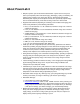
About PowerLab 6 Simple to operate: just connect PowerLab 6 between a power source and a pack, select a pack-specific preset and start charging, discharging, cycling or monitoring. No jumpers, plugs or dials to set! During Auto Charge, PowerLab 6 automatically determines pack capacity and sets optimal current, then dynamically adjusts charge rate as needed. Alternatively, select manual charge rates from 10mA to 40A.
PowerLab 6 Charge Control Software (CCS, a free download) allows you to customize, save and load presets (including data displays), and view real-time charging data and graphs. CCS also manages firmware updates to keep PowerLab 6 operating smoothly, and to keep you up-to-date with latest features and enhancements. Parallel charging takes advantage of the PowerLab 6’s high power output.
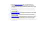
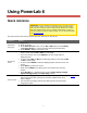
Using PowerLab 6 Quick reference IMPORTANT: To prevent damage to the power source, you must specify the power source’s voltage and current cutoffs before charging for the first time with a DC power supply, and before charging for the first time from a battery. After that, update the power source’s operating characteristics any time you change to a different DC power supply or battery. You can also specify cutoffs in the CCS Supply tab. This quick reference lists common PowerLab 6 tasks.
Charge, discharge, cycle or monitor a pack Charge packs in parallel 1. 2. 3. 4. Apply power and select power source (see above). Connect pack. Press INC or DEC to select desired User Preset, then press ENTER. For each question, press INC or DEC to select correct answer, then press ENTER. 5. CHECKING PACK indicates PowerLab 6 is attempting to detect attached pack. 6. Screen displays preset’s chemistry. If this matches pack’s chemistry, press ENTER to start.
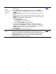
Set Smart Power Management IMPORTANT: To prevent damage to the power source, you must specify the power source’s voltage and current cutoffs before charging for the first time with a DC power supply, and before charging for the first time from a battery. After that, update the power source’s operating characteristics any time you change to a different DC power supply or battery. You can set a variety of operating options, including the very important power source voltage and current limits.
8. 9. 10. 11. 12. 13. 14. 15. 16. 17. 18. running multiple PowerLabs in Expansion Channel mode). If it doesn’t, press INC or DEC until you see PRIMARY CHANNEL. Press ENTER. At the Power Source? screen, press INC or DEC to select DC Power Supply, then press ENTER. At the Supply Current Limit? screen, press INC or DEC to specify the current limit appropriate for your DC power supply, then press ENTER. (Cutoff current should be slightly less than the power source’s maximum output current capability.
Set options Tip: A setting is saved as soon as you change it. Also, you don’t have to go through the entire sequence below—at any time, you can press and hold the BACK button to return to the User Preset menu. 1. Connect PowerLab 6 to a 10–32V DC power supply or Lead Acid battery. 2. Press any button on PowerLab 6’s panel. 3. At the Power Source? screen, use the INC or DEC button to select Battery or DC Power Supply (i.e., what is currently powering the PowerLab 6). 4.
Connect packs: basic Connect the pack to PowerLab 6’s Output jacks, Balance Port or both. The Balance Port accepts a 9-pin Cellpro balance connector, which supports packs up to 6s. If the pack has a different style balance connector, REVOLECTRIX offers a variety of adapters for most popular connector types and brands (visit the Cellpro Adapters section in the REVOLECTRIX Web site).
If stock REVOLECTRIX adapters don’t work for your packs, you can make your own adapters using the CPBP9P-10 Cellpro battery pigtail 10", 9 position, which consists of a 9-pin connector with un-terminated wires. See Balance connector wiring and the “CellPro Battery Wiring Diagram” available from the REVOLECTRIX Web site. Note: After a charge is initiated, never alter the connections between the charger and the battery packs. Always end the current charge session before making any connection changes.
Connect packs: advanced The table below lists several common PowerLab 6 charging configurations. Find the configuration that most closely matches how you want to charge, then click the “Details” link for more information.
Configuration B Summary: basic one-pack charging through balance and discharge wires. Components: 1 PowerLab 6 1 power source 1 standard adapter or Safe Adapter 1 pack Optional FUIM3 for computer support PowerLab 6 mode (Normal or Expansion Channel): Normal. PowerLab 6 maximum charge power: up to 1000W charge to one pack (6s) using 30VDC/1200W power source. Note: above illustrations may read “PowerLab 8” because for purposes of these illustrations, both models are identical.
Configuration C Summary: parallel charging. Components: 1 PowerLab 6 1 power source 1 Safe Parallel Adapter for each pack (do not use standard adapters) 2 or more packs (above 9 packs in parallel, you are responsible for determining the charge/discharge current for each pack) Optional FUIM3 for computer support PowerLab 6 mode (Normal or Expansion Channel): Normal.
Note: above illustrations may read “PowerLab 8” because for purposes of these illustrations, both models are identical.
Configuration D Summary: parallel charging split pack (10s or larger). Components: 1 PowerLab 6 1 power source 2 Safe Parallel Adapters 1 10s (or larger) split pack with center tap Optional FUIM3 for computer support PowerLab 6 mode (Normal or Expansion Channel): Normal. PowerLab 6 maximum charge power: up to 500W charge to each of two packs charged in parallel using 30VDC/1200W power source. Constraints: 1 pack side per adapter. Check pack polarity.
Note: above illustrations may read “PowerLab 8” because for purposes of these illustrations, both models are identical.
Configuration E Summary: two PowerLabs charging separate packs, one power source. Components: 2 PowerLabs 1 power source 2 standard adapters or Safe Parallel Adapters (1 adapter per pack) 2 packs (Safe Parallel Adapters require same cell count for both packs) 2 optional FUIM3s for computer support with 2 CCS instances PowerLab 6 mode (Normal or Expansion Channel): Normal. PowerLab 6 maximum charge power: up to 1000W to each pack (6s) using 30VDC/2400W power source.
Configuration F Summary: two PowerLabs charging separate packs, one power source, Expansion Channel Mode.
Configuration G Summary: two PowerLabs charging split pack (10s or larger), one power source, Expansion Channel Mode.
Note: above illustrations may read “PowerLab 8” because for purposes of these illustrations, both models are identical.
Configuration H Summary: two PowerLabs charging pack (10s or larger) with center tap, two power sources, Normal mode Components: 2 PowerLabs 2 ELECTRICALLY ISOLATED power sources: Lead Acid batteries or DC supplies (see note below) 2 standard adapters or Safe Parallel Adapters (1 adapter per side) 1 10s (or larger) pack with center tap User-provided jumper (see diagram) 2 optional FUIM3s for computer support with 2 CCS instances PowerLab 6 mode (Normal or Expansion Channel): N
Note: above illustrations may read “PowerLab 8” because for purposes of these illustrations, both models are identical.
Power supplies PowerLab 6 is one of the highest power RC battery maintenance devices available. Running full power, it can deliver 1000W to batteries during charge. To achieve this, even on a 6 cell Li battery, it must boost the input voltage. This means the PowerLab 6 may draw up to 1200W from the input power supply.
Charge/discharge/cycle/monitor a pack Tip: These detailed instructions will help you learn how to navigate through the charging process. For brief instructions, see the Quick reference. Once you become familiar with PowerLab 6 operations, you shouldn’t need instructions at all. IMPORTANT: To prevent damage to the power source, you must specify the power source’s operating characteristics before charging for the first time with a DC power supply, and before charging for the first time from a battery.
CHARGE ONLY (i.e., no discharge). DISCHARGE ONLY (i.e., no charge). MONITOR (no charge or discharge, just monitor cell voltages). n CYCLE (perform n charge/discharge cycles, as specified in preset). Tip: The number of cycles is specified in the preset. See Edit a User Preset to change the number of cycles or any other aspect of the preset. 6. PowerLab 6 displays CHECKING PACK to see whether a pack is connected. If a pack is connected, then... 7.
13. PowerLab 6 is ready to charge another battery (step 3). Start faster When following the instructions above, you probably noticed that PowerLab 6 asks a lot of questions before it starts a charge, discharge, cycle or monitor. That enables you to specify exactly what operations PowerLab 6 will perform. If all you want to do is Charge a battery, and once you have a preset configured properly, two settings in the CCS Options tab will speed up the process: Activate the Enable Quick Start option.
Charge/discharge/cycle packs in parallel PowerLab 6 can charge, discharge or cycle up to nine LiPo or A123 packs in parallel. Parallel operations can save a lot of time, but you must follow these rules: Always use Safe Parallel Adapters (available at the REVOLECTRIX Web site). Never use standard adapters. Connect only one pack per Safe Parallel Adapter.
Expansion Channel Mode In Normal Mode, multiple PowerLabs operate independently. Connect any number of PowerLabs to individual computer USB ports, and run multiple instances of CCS. Each PowerLab 6 communicates with a separate instance of CCS. In Expansion Channel Mode, multiple PowerLabs are connected via each unit’s PC port. Use this mode when you want to charge multiple, similar packs with reduced button presses.
5. On the Primary unit: a. Select the User Preset appropriate for all packs, then press ENTER. b. Answer all the questions and initiate charging. c. PowerLab 6 displays CHECKING PACK to see whether a pack is connected at each unit. If packs are connected, then... d. Verify that the preset chemistry matches the packs’ chemistries by pressing ENTER. 6. During charging: Press INC or DEC on the Primary unit to view charging data. Data will be displayed on each PowerLab 6 for the pack connected to that unit.
Regenerative discharge Regenerative discharge routes most of the energy from the pack being discharged back into the Lead Acid battery powering the PowerLab 6. This feature is only available when the PowerLab 6 is powered from a Lead Acid battery. Regenerative discharge supports up to 40A, 1000W maximum. Regenerative discharge Enable/disable regenerative discharge at the PowerLab 6 via Smart Power Management for the supply battery.
Modify a preset You can change many preset properties directly at PowerLab 6. Use this procedure at any time, but it’s essential when PowerLab 6 isn’t connected to the Charge Control Software. Tip: You can also use the Charge Control Software’s Presets tab to hide, show, re-arrange, copy and modify presets. 1. In the User Preset menu, use INC or DEC to select the preset you want to modify. Press and hold INC or DEC to scroll rapidly. 2. Press INC+DEC to access options. 3.
Manage presets On PowerLab 6 you can: Clear a User Preset. Copy a Library Preset for use as a User Preset. Tip: You can also use the Charge Control Software’s Presets tab to hide, show, re-arrange, copy and modify presets.
1. In the User Preset menu, use INC or DEC to select the slot where you want the new preset. Selecting an EMPTY PRESET is usually better unless you are intentionally overwriting an existing preset. Press and hold INC or DEC to scroll rapidly. 2. Press INC+DEC to access options. 3. In the Choose TASK? screen, press INC until you see Manage Presets, then press 4. 5. 6. 7. 8. 9. ENTER. In the Clear Current Preset? > N screen, press ENTER.
Using the Charge Control Software About the CCS The free PowerLab 6 Charge Control Software (CCS) gives you unparalleled ability to customize the PowerLab 6. In order to connect the PowerLab 6 to the computer and use the CCS, you are required to use one of the FMA PC USB Interfaces; either the FUIM2 or the FUIM3. This table lists common CCS tasks. What do you want to do? To do this... Go here...
Installing the CCS Install the Charge Control Software (CCS) from the PowerLab 6 Software Install page (in the REVOLECTRIX Web site) using one of the methods detailed there. PowerLab 6 CCS is available at the PowerLab 6 CCS Install page. Once the software is installed, it will automatically check the Web site for updates in the background each time it is started. The next time you launch the CCS, it will ask you if you want to upgrade to the latest version.
Cells tab Monitor charge and discharge data in the Cells tab. You can also select a preset and start/stop PowerLab 6 operations in this tab. Operating from the Cells tab 1. Connect the pack to the PowerLab 6. 2. In the Cells tab, open the User Preset menu (near the bottom of the tab), then select the preset you want to use for charging. Selecting a preset here also selects it on the PowerLab 6. 3. To change the selected preset’s settings: a. Click the Edit button.
Tip: Hover the cursor over each data line for a brief description. Monitor progress in graphs. To stop operations: Click the STOP button. This ends the charge session and clears and data collected during the operation. Or: 10. When the operation is complete, PowerLab 6 will “beep beep beep” several times. Note: NiMH, NiCd and Lead Acid User Presets may switch to trickle charge (depending on how the preset is configured) when charging is complete. 11. Disconnect the pack from PowerLab 6.
Internal Resistance tab The Int. Res. tab displays cell internal resistance when charging LiPo and A123 balanced packs. Internal resistance is not calculated or displayed during discharge cycles. Note: Internal resistance can only be measured on packs with a state of charge below 75% of capacity. It takes less than 3 minutes to calculate internal resistance. Internal resistance can only be calculated during charging.
Supply tab Use the Supply tab to: Set the default power source type. Specify power source voltage and current limits. Monitor power source voltage, current and wattage. DC Power Supply section Enabled: If checked, a DC power supply is the selected power source. Supply Low Voltage Limit: Set to a value just below the power supply’s normal output voltage. If the supply voltage falls below this level, PowerLab 6 operations will stop. If the voltage drops fast enough, the PowerLab 6 may reboot.
Battery Max Amps Out: Set for maximum supply battery current draw. If the charge rate is set higher than the input current allows, the PowerLab 6 will draw no more than the level set here, which may limit output current to the pack. If Battery Max Amps Out is set too high, the battery’s output voltage may drop below the Battery Low Voltage Out setting and charging will stop and the input battery could be damaged from excessive current draw.
Firmware tab The Firmware tab enables you to: Determine the firmware currently installed in the PowerLab 6: it is displayed in the center of the tab. (Firmware version is also displayed on the PowerLab 6 power-on “welcome” screen.) Install the latest firmware version. Download and install the latest Library Presets. Restore the factory presets and options. To update PowerLab 6’s firmware: Tip: You can display similar instructions in the Firmware tab by clicking Click to view instructions. 1.
Full firmware and preset update process Over time, new CCS versions and new factory default presets will be released. These changes may correct safety violations or provide enhanced capabilities that would cause older presets to contain errors when running in newer firmware or CCS software. This procedure enables you to update your custom presets as well as the firmware: 1. Back up your custom presets one at a time using the File > Save Preset X to File command. 2.
Options tab In the Options tab you can: Specify how information appears in PowerLab 6’s display. Control whether preset changes made at the PowerLab are uploaded to the CCS. Specify speaker volume and beep settings. Set startup options. Save and load option sets. Note: After changing anything in the Options tab, click the Update button to download the changes to PowerLab 6. Visual Settings section Cells Scroll Seconds: Set time for cell data to display during charging.
convention on the balance port. When set to XH/EH Wiring, PowerLab looks for the JST XH/EH wiring convention on the balance port. See FMA Wiring mode vs. XH/EH Wiring mode later in this user guide for more details. Enable Quick Start: When checked, you can skip over a preset’s questions regarding charge/discharge current, available modes of operation—just press and hold ENTER—when preparing to charge a pack at the PowerLab 6.
Presets tab The Charge Control Software gives you almost total control over User Presets, including which ones are available in PowerLab 6, the order in which they are displayed, charging characteristics and the content and order of data screens displayed during charging. Edit a User Preset 1. If the Advanced Properties option is checked, uncheck it. (See “Advanced properties,” below, for more information about this option.) 2. In the left panel, click the User Preset you want to edit.
Save, load, backup and restore User Presets To save a User Preset: 1. In the Presets tab, click the User Preset you want to save. The selected preset will have a gray background. 2. File > Save Preset X to File... . This opens the Save a Preset dialog. 3. Navigate to the Folder where you want to save the file. 4. (Optional) Overwrite the default preset file name (this doesn’t change the preset’s display name). 5. Click the Save button.
To restore all User Presets from an archive: Note: This operation will overwrite all User Presets. 1. In any tab, File > Restore All User Presets... . This opens the Restore User Presets dialog. 2. Navigate to the Folder where the archive file is stored. 3. Click the archive file. 4. Click the Open button. 5. Click the Update button to download User Presets to PowerLab 6. Tip: Use the Backup and Restore commands when you want to completely change the PowerLab 6’s operations.
Errors tab The Errors tab lists preset errors detected by the CCS. If there are no preset errors, the tab is labeled No Errors. If there are preset errors present in the current CCS preset list, the tab is labeled X Errors, where X is the total number of errors found in all loaded presets. To correct a preset error: In the Errors tab, double-click the error description. CCS displays the corresponding location in the preset’s properties list.
Graphs CCS graphs enable you to see how battery performance changes over time during charging and discharging operations. When you start a charge, CCS opens a dialog in which you can name the graph. Enter a descriptive name, then click OK. Note: At this point, the graph is being recorded in your computer’s memory. It is not yet saved to the hard drive. To set graph update interval: In the main CCS window, View > Preferences > Graphing Update Rate.
After you generate a graph, perform the following operations in the main CCS window. To save graph data: File > Save Graph. (This saves all data, not just the data currently displayed in the graph.) Tip: Unless graphing has been disabled, the CCS will prompt you to name a Graphing session each time a charge/discharge/monitor/cycle operation is started.
Generate a custom fuel table PowerLab 6 calculates the fuel level in a battery based on a lookup table for a particular cell manufacturer or chemistry. Even two LiPo batteries from different eras or different brands from the same era can have vastly different voltage-versus-time characteristics during charging. When the fuel table doesn’t match the cell’s chemical composition, errors in the fuel reading occur. To read more, see the section How Auto Current Mode works in this user guide.
Run multiple CCS instances You can run multiple instances of CCS on one computer to support multiple PowerLabs. Here’s how: 1. 2. 3. 4. Connect the first PowerLab 6 to the computer using an FUIM3. Launch CCS. Waiting to Start should appear at the top of the CCS window. Connect the next PowerLab 6 to the computer using another FUIM3. Launch CCS again (this will be the second instance). Waiting to Start should appear at the top of the CCS window.
Other information Charging tips General information Because PowerLab’s cell balancing technology monitors individual cells, you don’t need to cool a pack before charging it. Go from flying to charging to flying again without waiting. Cells in a pack have different voltages when they are discharged. PowerLab 6 balances (equalizes) cell voltages while it is charging the pack. REVOLECTRIX chargers provide the highest available balance current in the industry: up to 1A, and now customer-adjustable.
different number of cells together in parallel. This is less a function of the PowerLab 6 and more about assuring proper connection of packs to the PowerLab 6.) If a pack is at 80% or less of its capacity when connected to an auto-detect speed controller, the controller may lower its cut-off voltage. This could over-discharge the pack during the flight. Auto-detect speed controllers should properly set cut-off voltage if packs are charged to at least 90%.
How Auto Current Mode works PowerLab 6’s Auto Current Mode (indicated by the charge rate Ax.0C) precisely monitors individual cell fuel levels (cell voltages) in a LiPo, Li-Ion or A123 pack. If PowerLab 6 determines it is charging too fast, it slows down. Likewise, if it is charging too slow, it speeds up. PowerLab 6 adjusts charge current at one minute intervals throughout the charge cycle.
Estimating performance factors If you don’t have a way to directly measure your propulsion system’s electrical parameters, PowerLab 6 enables you to estimate them using before-and-after flight measurements. Note: The calculations outlined below work best when the pack is charged using a custom fuel table. They may be invalid if the fuel table does not match the pack under test. 1. Collect data. a. Charge pack. b. When charging is finished, record Fuel % and total pack voltage (i.e. sum of cell voltages).
FMA Wiring mode vs. XH/EH Wiring mode By default, the PowerLab 6 ships with the balance connector (output) set for FMA’s Cellpro wiring. This wiring mode supports all Cellpro REVOLECTRIX brand batteries and adapters directly. However, due to the proliferation of the JST XH/EH balance connectors available on many LiPo battery packs in the R/C industry, the PowerLab also supports the popular XH/EH Wiring mode for the balance connector.
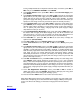
Balance connector wiring When using FMA Wiring mode (Factory Default Setting) The following diagrams shows how a 9 pin Cellpro (JST PA series) balance connector (REVO PN CPBP9P-10-US) must be wired to a 6s, 5s, 4s, 3s, 2s, and 1s battery pack when the PowerLab 6 is set to FMA Wiring mode (Factory default).
5s Pack Pack positive (red), 18.5V* Red Pack positive Cell 5 Node 4, 14.8V* Node 4 Cell 4 Node 3 Node 2 Node 1 Pin 1 Black Pack negative Node 3, 11.1V* Cell 3 Node 2, 7.4V* Cell 2 Node 1, 3.7V* Cell 1 Pack negative (blk), 0V * Nominal voltage with respect to pack negative FMA Cellpro Connector/FMA Wiring Mode 4s Pack Pack positive (red), 14.8V* Red Pack positive Cell 4 Node 3 Node 2 Node 1 Pin 1 Black Pack negative Node 3, 11.1V* Cell 3 Node 2, 7.4V* Cell 2 Node 1, 3.
3s Pack Pack positive (red), 11.1V* Red Pack positive Node 2 Node 1 Pin 1 Black Pack negative Cell 3 Node 2, 7.4V* Cell 2 Node 1, 3.7V* Cell 1 Pack negative (blk), 0V * Nominal voltage with respect to pack negative FMA Cellpro Connector/FMA Wiring Mode 2s Pack Pack positive (red), 7.4V* Red Pack positive Node 1 Pin 1 Black Pack negative Cell 2 Node 1, 3.
1s Pack Pack positive (red), 3.
When using XH/EH Wiring mode These diagrams show how a 9 pin Cellpro (JST PA series) balance connector (REVO PN CPBP9P-10-US) must be wired to a 6s, 5s, 4s, 3s, 2s, and 1s battery pack when the PowerLab 6 is set to XH/EH Wiring mode. You may choose to set the PowerLab 6 to XH/EH MODE and splice the 9 pin Cellpro pigtail to an XH/EH adapter you already own. Use these illustrations to guide you.
5s Pack Pack positive, 18.5V* Pack positive Node 4 Cell 5 Node 4, 14.8V* Cell 4 Node 3 Node 2 Node 1 Pin 1 Black Pack negative Node 3, 11.1V* Cell 3 Node 2, 7.4V* Cell 2 Node 1, 3.7V* Cell 1 Pack negative (blk), 0V * Nominal voltage with respect to pack negative FMA Cellpro Connector/XH and EH Wiring Mode 4s Pack Pack positive Pack positive, 14.8V* Cell 4 Node 3 Node 2 Node 1 Pin 1 Black Pack negative Node 3, 11.1V* Cell 3 Node 2, 7.4V* Cell 2 Node 1, 3.
3s Pack Pack positive Node 2 Node 1 Pin 1 Black Pack negative Pack positive, 11.1V* Cell 3 Node 2, 7.4V* Cell 2 Node 1, 3.7V* Cell 1 Pack negative (blk), 0V * Nominal voltage with respect to pack negative FMA Cellpro Connector/XH and EH Wiring Mode 2s Pack Pack positive Node 1 Pin 1 Black Pack negative Pack positive, 7.4V* Cell 2 Node 1, 3.
1s Pack Pack positive Pin 1 Black Pack negative Pack positive, 3.
Open architecture presets PowerLab 6 can be described as being “preset driven.” All major aspects of its operation are defined as parameters at the preset level. The fact that you (for the most part) can set these parameters introduces the concept of “open architecture presets.” As an example of how preset parameters affect the charging process, each Auto mode preset includes a Fuel Table unique to a specific battery chemistry.
LiPo factory presets LiPo Generic Accurate Charge Basic LiPo preset can be used for any LiPo battery. Fuel Table is optimized for generic LiPo batteries from C discharge ratings up to 20C. Selectable charge rates include 1C, 2C, 3C AUTO or 10 mA to 10.0A manual. Optimization is for the most accurate charging with termination settings of C/20 and max of 30 min timeout for C.V. mode. This pre-set requires that every cell in the battery is charged to exactly 100%.
LiPo Generic Small Balanced Special LiPo preset designed for charging small batteries but still using balance connector. This preset is recommended for battery sizes as small as 10 mAh and up to 500 mAh. Preset requires manual charge rate settings of between 10 and 500 mA in 5 mA increments by default. Optimization is for the most accurate charging with termination settings of C/20 and max of 30 min timeout for C.V. mode. This preset requires that every cell in the battery is charged to exactly 100%.
A123 factory presets A123 2300 mAh Accurate Charge Optimized for balance charging A123, 2300 mAh battery packs (requires balance wires on the pack). Fuel Table is optimized for this specific battery type and capacity. Selectable charge rates include 1C, 2C, 3C, 4C, 5C AUTO or 10 mA to 10A manual. Optimization is for the most accurate charging with termination settings of C/20 and max of 30 min timeout for C.V. mode. This preset requires that every cell in the battery is charged to exactly 100%.
when-ever possible. This preset may also be used for LiFePO4 type batteries which have similar charge characteristics. When using LiFePO4 batteries, Fuel Gauge readout may not be accurate and AUTO charge rate may be higher or lower than expected. Max Auto Amps parameter is default to 5A for this preset which means that unless you alter it, this preset will not exceed 5A max charge rate during AUTO charge. Default charge rate setting is 4.6A manual.
expected. Default charge rate setting is 3.3A Manual. Max Auto Amps parameter is default to 6A for this preset which means that this preset will not exceed 6A max charge rate during AUTO charge. Other defaults: discharge rate setting is 1A, discharge voltage 2.8V/cell. A123 1100 mAh Non Bal. 1-5s Optimized for non-balance charging A123, 1100 mAh battery packs (balance wires not required on the pack). Fuel Table is optimized for this specific battery type and capacity.
of C/20 and max of 15 min timeout for C.V. mode. This preset does not require that every cell in the battery is charged to exactly 100%. If using A123 1100 mAh or LiFePO4 batteries, Fuel Gauge readout may not be accurate. Default charge rate setting is 2.2A. Other defaults: discharge rate setting is10A, charge voltage 3.335V/cell, discharge voltage 3.32V/cell. A123 Store Non Bal. 1-5s Special A123 preset (any capacity) designed to storage charge or discharge a nonbalanced battery up or down to 3.
NiMH, NiCd and Lead Acid factory presets NiCd Fast Charge with Trickle Basic NiCd Fast Charge with Delta Peak Cutoff and Trickle Charge. Requires manual charge rate setting of between 10 mA and 20A, with default value of 1A. Can charge from 1 to 21 cell packs. Fallback default setting is 8mV. Trickle charge rate is 1/20C of the charge rate setting. Charge will timeout in 4 hrs if peak is not reached. Trickle charge timeout is set for 1 Day. This preset is for constant current charging applications only.
Specifications: For Battery types: Lithium Polymer (1s to 6s balanced, 1s to 2s unbalanced), Lithium Ion (1s to 6s balanced, 1s to 2s unbalanced), Lithium Manganese (1s to 6s balanced, 1s to 2s unbalanced), A123 (LiFePO4) (1s to 6s balanced, 1s to 8s unbalanced), NiCd (1s to 19s), NiMH (1s to 19s), 6v, 12v, 24v Lead Acid batteries (Flooded, Gel, AGM, SLA) Pack capacity: 20 mAh to 360Ah Input voltage: 10-32VDC, reverse polarity protected Input current: 1A to 40A, software limited Power conversion: Synchronou
Footnotes: * Please note, for safety reasons, available charger current may be limited for certain battery types and/or charging modes, e.g.
Troubleshooting Operating errors appear as safety codes in the display. If possible, correct the error. If errors continue, contact FMA Customer Service. Safety Code/Message Problem Increase Supply Supply <10 Volts Supply >32 Volts Supply Unstable Preset not 6S Bad Preset Version NiCd/NiMH charging can’t maintain constant current Supply voltage is too low Supply voltage is too high Check connections.
Bananas Removed Negative Amps The bananas were removed when charging Check the supply wiring Chg. Not Allowed Cell V. Too Hi/L Pack Below 3.0V REPLACE BAD PACK Exp. Ch Com. Err The preset will not allow charging The cell voltage is out of range The pack voltage is too low.
Safety Code #119 Safety Code #120 Bananas connected while charging Cell count not verified Safety Code #121 Safety Code #122 Safety Code #123 Safety Code #124 Safety Code #125 Safety Code #126 Shunt FET off while CHG/DSCHING Unknown chemistry No next charge screen to show Bad run screen number Cell count is zero Serial0 recursive overflow Safety Code #127 Safety Code #128 Safety Code #129 Safety Code #130 Safety Code #131 Safety Code #132 Discharge mode timeout Peek detect set past 15 minutes NiCd/NiMH
Support options For Sales Support on REVOLECTRIX Brand Products: Email: sales@revolectrix.com or phone: (301) 798-2770 For Sales or Technical Support on "Other Brands" in the REVO Store: Email: brandsupport@revolectrix.com To request information about a REVOLECTRIX product you are considering purchasing: Email: info@revolectrix.
REVOLECTRIX limited warranty REVOLECTRIX warrants this product to be free of manufacturing defects for the term of one year from the date of purchase. Should any defects covered by this warranty occur, the product shall be repaired or replaced with a unit of equal performance by REVOLECTRIX or an authorized REVOLECTRIX service station. Unit must be returned to the original place of purchase.