
REVLC06S40A-SPA-MC Revolectrix PowerLab 6 Manual

65
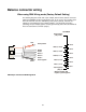
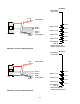
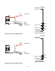
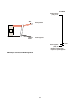
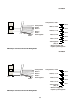
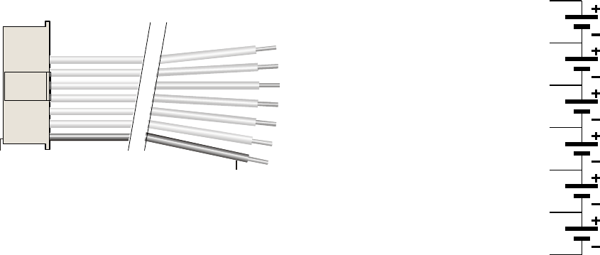
When using XH/EH Wiring mode
These diagrams show how a 9 pin Cellpro (JST PA series) balance connector (REVO
PN CPBP9P-10-US) must be wired to a 6s, 5s, 4s, 3s, 2s, and 1s battery pack when the
PowerLab 6 is set to XH/EH Wiring mode. You may choose to set the PowerLab 6 to
XH/EH MODE and splice the 9 pin Cellpro pigtail to an XH/EH adapter you already own.
Use these illustrations to guide you. Whether the following is accomplished via the
available adapters, or by physically connecting (soldering) the 9 pin Cellpro pigtail to a
battery pack directly, this is what the PowerLab must see at its balance connector
(output):
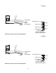
Pin 1
Black
Node 5
Pack positive
Node 4
Node 3
Node 2
Node 1
Pack negative
6s Pack
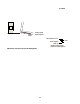
Node 4, 14.8V*
Node 5, 18.5V*
Pack positive, 22.2V*
Node 3, 11.1V*
Node 2, 7.4V*
Node 1, 3.7V*
Pack negative
(blk), 0V
Cell 5
Cell 6
Cell 4
Cell 3
Cell 2
Cell 1
* Nominal voltage with
respect to pack negative
FMA Cellpro Connector/XH and EH Wiring Mode