User-Manual Gateway componet for EtherCAT PR100038 • 1/7/2016
Table of Contents KUNBUS GmbH Table of Contents 1 General Information ........................................................................................................................ 3 1.1 Disclaimer.................................................................................................................................. 3 1.2 Notes Regarding this User Manual............................................................................................ 4 1.3 Validity ..........................
1.1 Disclaimer © 2015 KUNBUS GmbH, Denkendorf (Germany) The contents of this user manual have been prepared by KUNBUS GmbH with the utmost care. Due to technical development, KUNBUS GmbH reserves the right to change or replace the contents of this user manual without prior notice. You can always obtain the latest version of the user manual at our homepage: www.kunbus.de KUNBUS GmbH shall be liable exclusively to the extent specified in General Terms and Conditions (www.kunbus.de/agb.html).
This user manual provides important technical information that can enable you as a user to integrate the Gateways into your applications and systems efficiently, safely and conveniently. It is intended for trained, qualified personnel, whose sound knowledge in the field of electronic circuits and expertise in EtherCAT ® is assumed. As an integral part of the module, the information provided here should be kept and made available to the user. 1.
Safe Use 2 Safe Use 2.1 User The Gateway may only be assembled, installed and put into operation by trained, qualified personnel. Before assembly, it is absolutely essential that this documentation has been read carefully and understood. Expertise in the following fields is assumed: – electronic circuits, – basic knowledge of EtherCAT, – work in electrostatic protected areas, – locally applicable rules and regulations for occupational safety. 2.
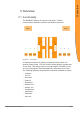
Overview 3 Overview 3.1 Functionality The KUNBUS Gateway is a protocol converter. It allows communication between networks with different protocols. Illustration 1: Functionality A Gateway consists of 2 gateway components that master one specific protocol each. You can combine these gateway components as you wish. This design offers you a high degree of flexibility, since you can exchange the individual gateway components at any time.
Overview 3.
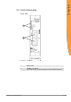
Overview Top 1 1 2 Illustration 3: Top 1 2 Gateway-component EtherCAT Interconnect ports for interconnecting the gateway components. Locking clamps for securely attaching the gateway component to the DIN rail.
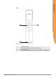
Overview Bottom 1 2 Illustration 4: Bottom 1 2 Gateway-component EtherCAT Mains connection with 24 V power supply Locking clamps for securely attaching the gateway component to the DIN rail.
The gateway component is equipped with 5 status LEDs. The LED Power provides information about the state of the gateway component. The other LEDs provide information about the EtherCAT status.
(green) off flickers (50 ms on / 50 ms off) on L/A 2 (EC OUT) off flickers (green) (50 ms on / 50 ms off) on Gateway-component EtherCAT No connection Connection and data traffic Connection No connection Connection and data traffic Connection 11 / 30 Overview L/A 1 (EC IN)
Installation 4 Installation 4.1 Preparations for Trouble-free Operation In the following section we have compiled some general information for you that is important for trouble-free operation. If you are already acquainted with this topic, you can skip to the next section. There, you will learn about which conditions are necessary for installing the gateway. Cable routing Route your cables separately in cable groups. This will protect your gateway from any unintended electromagnetic interferences.
Shield your cables. This will reduce any unintended electromagnetic interferences. Potential equalization Potential differences occur when devices are connected to different earths. These potential differences cause malfunctions. To prevent malfunctions, you have to route an equipotential equalization conductor. When doing so, bear in mind the following points: – Select an equipotential equalization conductor with low impedance.
The Gateway was designed for use in a control cabinet. ü The protection class of the control cabinet must be equivalent to at least IP54. ü For installation in the control cabinet you need a DIN rail 35 x 7.5 mm (EN50022). ◦ Install the DIN rail horizontally in the control cabinet according to the manufacturers' specifications. When doing so, make sure that the Gateway is at a sufficient distance from other devices. NOTICE Your gateway could be damaged if temperatures are too high.
In order to attain a fully functional gateway, you have to interconnect both gateway components. ◦ Connect an interconnect port to each gateway component using the plug-in jumper provided. Illustration 6: Connecting gateway components ð You can now install the gateway in the control cabinet. NOTICE Only ever interconnect 2 gateway components. If you connect additional components, severe defects could result on all devices. Gateway-component EtherCAT 15 / 30 Installation 4.
◦ Hold the raster element of the gateway on the DIN rail. ◦ Press down the locking elements towards the gateway. ◦ Make sure that the gateway is firmly attached to the DIN rail. Gateway-component EtherCAT 16 / 30 Installation 4.
To connect the gateway component to the power supply, you need a spring-loaded terminal (e.g. Metz-Connect SP995xxVBNC). You have to connect each gateway component separately to a power supply. Never interconnect functional earth and GND, otherwise the galvanic isolation between gateway GND and fieldbus ground will be removed. Instead, connect the functional earth with low impedance to the potential equalization.
To connect the gateway component to EtherCAT, you need Two RJ45 connectors. The pin assignment complies with the Ethernet standard. Pin 1 2 3 4 5 6 7 8 Gateway-component EtherCAT Assignment TX+ TXRX+ Not assigned. Pin 4 and 5 are interconnected and laid via a filter on PE for better EMC response. RXNot assigned. Pin 7 and 8 are interconnected and laid via a filter on PE for better EMC response. 18 / 30 Installation 4.
5.1 Supported Size of the Process Data The gateway component for EtherCAT supports an input and output area of 512 bytes each: NOTICE Bear in mind that the maximum length of the process data is always determined by the fieldbus with the shorter data length. Example: EtherCAT supports 512 bytes PROFIBUS supports 488 bytes In conjunction with EtherCAT / PROFIBUS this means that 488 bytes are transmitted and updated cyclically.
To configure the gateway component, you have to perform the appropriate settings with the configuration software of your EtherCAT Master. You can use the objects listed below to configure the gateway component. 5.
U8 RW Assigned object #1 Assigned object #2 Assigned object #3 Assigned object #4 Assigned object #5 Assigned object #6 … Assigned object #128 Number of assigned objects U32 U32 U32 U32 U32 U32 U32 U32 U8 RW RW RW RW RW RW RW RW RW Assigned object #1 Assigned object #2 Assigned object #3 Assigned object #4 Assigned object #5 Assigned object #6 … Assigned object #128 Number of entries Mailbox Out Mailbox In Outputs Inputs Number of entries U32 U32 U32 U32 U32 U32 U32 U32 U8 U8 U8 U8 U8 U8 U16 U16 U16 U
The output data (512 bytes) can be accessed byte-wise, word-wise and double word-wise. The same data area is accessed here. Example: 2000h:01h to 2000h:04h maps the same data as 2010h:01h until 2010h:02h and the same data as 2020h:01h NOTICE Gateway component only transfers fieldbus data to the partner gateway component if it is in "Operational" EtherCAT status. Otherwise, "zeros" are transmitted to the partner gateway component.
Gateway-component EtherCAT U8 U16 RO RO U8 U16 RO RO U8 U16 RO RO U8 U16 RO RO Configuration 2010 h Output Buffer 00 h Number of entries 01 h Output Buffer Word #0 02 h Output Buffer Word #1 ... ... 40 h Output Buffer Word #63 2011 h Output Buffer 00 h Number of entries 01 h Output Buffer Word #64 02 h Output Buffer Word #65 ... ... 40 h Output Buffer Word #127 2012 h Output Buffer 00 h Number of entries 01 h Output Buffer Word #128 02 h Output Buffer Word #129 ... ...
Gateway-component EtherCAT U8 U32 RO RO U8 U32 RO RO U8 U32 RO RO U8 U32 RO RO Configuration 2020 h Output Buffer 00 h Number of entries 01 h Output Buffer Double Word #0 02 h Output Buffer Double Word #1 ... ... 20 h Output Buffer Double Word #31 2021 h Output Buffer 00 h Number of entries 01 h Output Buffer Double Word #32 02 h Output Buffer Double Word #33 ... ...
Configuration Fieldbus input data (from the master) Index 2100 h 2101 h 2102 h 2103 h Object Name Sub- Description index Input Buffer 00 h Number of entries 01 h Input Buffer Byte #0 02 h Input Buffer Byte #1 ... ... 80 h Input Buffer Byte #127 Input Buffer 00 h Number of entries 01 h Input Buffer Byte #128 02 h Input Buffer Byte #129 ... ... 80 h Input Buffer Byte #255 Input Buffer 00 h Number of entries 01 h Input Buffer Byte #256 02 h Input Buffer Byte #257 ... ...
Input Buffer 00 h 01 h 02 h ... 40 h 2111 h Input Buffer 00 h 01 h 02 h ... 40 h 2112 h Input Buffer 00 h 01 h 02 h ... 40 h 2113 h Input Buffer 00 h 01 h 02 h ... 40 h Gateway-component EtherCAT Number of entries Input Buffer Word #0 Input Buffer Word #1 ... Input Buffer Word #63 Number of entries Input Buffer Word #64 Input Buffer Word #65 ... Input Buffer Word #127 Number of entries Input Buffer Word #128 Input Buffer Word #129 ...
Input Buffer 00 h 01 h 02 h ... 20 h 2121 h Input Buffer 00 h 01 h 02 h ... 20 h 2122 h Input Buffer 00 h 01 h 02 h ... 20 h 2123 h Input Buffer 00 h 01 h 02 h ... 20 h Gateway-component EtherCAT Number of entries Input Buffer Double Word #0 Input Buffer Double Word #1 ... Input Buffer Double Word #31 Number of entries Input Buffer Double Word #32 Input Buffer Double Word #33 ... Input Buffer Double Word #63 Number of entries Input Buffer Double Word #64 Input Buffer Double Word #65 ...
You can poll the status of the other gateway component by SDO entry in the OBD. Index Object Name 0x2200 Status of the partner gateway component Sub- Description index 00 h Number of entries 01 h Length of the input data 02 h Length of the output data 03 h Module Type 04 h Gateway-component EtherCAT Data Access type U8 RO Remark RO max. 512 bytes U16 RO max. 512 bytes U16 RO 74 (EtherCAT Gateway Component) 0x00 Fieldbus not connected.
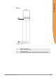
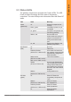
Technical Data 6 Technical Data 6.1 Technical Data Dimensions Width Height Depth Weight 22.5 mm 96 mm 110.4 mm 90 g Electrical data Power supply 24 V DC Power consumption during operation 100 mA (cyclical data exchange) Status display LED Environmental conditions Ambient temperature Storage temperature Humidity Condensing Protection class 0 – 60 °C - 25 – 60 °C 93 % (at 40 °C) Not allowed Control cabinet IP54 Housing IP20 Terminal area IP20 Assembly data DIN rail Height Depth 35 x 7.
Technical Data Illustration 7: Side dimensions Illustration 8: Front dimensions Gateway-component EtherCAT 30 / 30