
Operation Guide


2 INSTALLATION GUIDE
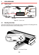
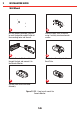
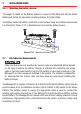
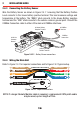
2.4 The Manager30 Wiring Connections
REDARC recommends that this unit be installed by a suitably qualified person.
The AC power connection must be connected to an earthed socket outlet. Do not use
The Manager30 AC input if the cord is damaged. Use of a non-genuine or damaged
AC input cord may result in a risk of fire, electric shock, or injury to persons. (If
the supply cord is damaged, it must be replaced by the genuine REDARC part or
assembly available from the manufacturer or service agent).
Always wire the Output Connector before connecting it to the Main Unit. During
connection of the unit, the Battery Output (positive) must be connected first, followed
by the Ground (chassis) terminal. The chassis connection should be made away
from the battery and fuel lines. DC Input (positive) should be connected last. Once all
connections are wired to the Output Connector, plug the connector into the Main Unit.
When disconnecting remove the Output Connector from the Main Unit first. The DC
Input should be disconnected next, followed by the Ground (chassis) connection,
then the Battery Output connection.
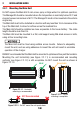
2.4.1 Load Disconnect Feature
The Load Disconnect wire is a ground switch to activate a relay for disconnection of any
loads running from the house battery. The relay must be 12V with a maximum coil current
of 1A and resistor or diode suppression is recommended. The Load Disconnect feature
must be activated in the User Menu as explained in Section 3.5 of this manual.
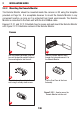
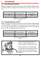
2.4.2 Ignition Trigger Feature
The Ignition Trigger wire is used to turn the DC charging source on with ignition. In most
circumstances this wire does not need to be connected. This feature is designed to allow
vehicle with Variable Voltage alternators to trigger the DC Input. Figure 2.4.2 shows how
to wire the Ignition Trigger wire.
The Ignition Trigger feature must be activated in the User Menu as explained in Section
3.5 of this manual.
18