
Operation Guide


2 INSTALLATION GUIDE
MODEL
AC INPUT
VEHICLE INPUT
SOLAR INPUT
BATTERY OUTPUT
BMS1230S3
230V, 50-60Hz, 560W
9 - 32VDC, 520W
9 - 32VDC, 520W
12VDC Nom./ 0-30A
Please refer to owners
manual for appropriate wire
gauge and fuse ratings.
The Redarc CAN system is
designed to operate Redarc
CAN based devices only.
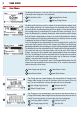
WARNING: Before obtaining access to terminals, all supply circuits must be disconnected
30
AMPS
LITHIUM
PROFILE
PROFILE
L
iFe
PO
4
Solar
Panel
50A
Fuse
Not
supplied
Start
Battery
Remote
Monitor
BMS1230S3
+
+
+
Mains AC from
mains power
(rear side)
AC
MAINS
-
+
House
Battery
1 2
3
4
5
6
Battery
Sensor
40A
Fuse
Not
supplied
Ignition
Trigger
SBI12-BLD
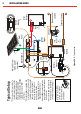
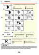
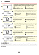
Typical Setup
*1 The size of this fuse relates to
the total current draw of all the
loads connected to the House
Battery, and should be rated
slightly higher than this. REDARC
recommend the use of MIDI
Style Fuses.
*2 Essential loads are loads which
must be left on at all times, until
the battery is flat. Non-essential
loads are those switched off
when the battery reaches a
particular low-charge
level,which can be set in the
‘Advanced Settings’ menu.
*3 Both CANBus connections can
be used for either the Display or
Battery Sensor
*4 Ensure the RED terminal on the
Battery Sensor is connected to
the Battery Positive Terminal.
A single fuse and holder
setup from the Fuse Kits
available from REDARC.
Part number FK40 (40A)
or FK60 (60A).
*4
Essential Loads*2
Non-essential
Loads*2
Load
Fuses
Not
supplied
*1
*3
*3
Figure 2.4.2 - Typical setup.
20