THE MANAGER Battery Management System BMS1230S3
THE MANAGER30 The Manager30 Battery Management System is a complete charging solution for your Lead Acid or LiFePO4 Auxiliary or House battery. The system incorporates 12V Solar, 240V AC and 12/24V DC inputs to provide a 12V charging output at a maximum 30A rating. The system also includes a Remote Monitor which provides information such as current, voltage and temperature as well as a simplified battery percentage and charge rate.
WARNINGS & SAFETY INSTRUCTIONS 8. 9. 10. 11. 12. 13. 14. a) b) c) d) e) 1. 2. 3. 4. 5. 6. 7. 8. Do NOT try to charge non-rechargable batteries. When using the Battery Charger to charge a Lithium Iron Phosphate battery, only batteries that feature an inbuilt battery management system featuring inbuilt under and over voltage protection and cell balancing are suitable. NEVER smoke or allow a spark or flame in vicinity of battery. This may cause the battery to explode.
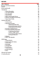
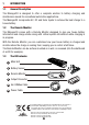
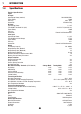
CONTENTS Table of Contents Warnings and Safety Instructions Contents Features and Benefits Page 01 03 04 1 Introduction 1. General Description 2. The Remote Monitor 3. The Kit Includes 4. Specifications 5. Multi-stage Charging Process 6. Maximum Charging Current Setting 7. Green Power Priority 05 05 05 05 06 08 10 10 2 INSTALLATION Guide 1. System Layout 2. Mounting Instructions 1. Mounting the Main Unit 2. Mounting the Remote Monitor 3. Mounting the Battery Sensor 3.
FEATURES AND BENEFITS 1. The Manager30 incorporates six products in one, it’s a DC-DC charger, a 240-volt charger, a solar charger, a dual battery isolator, a load disconnect controller and a remote battery monitor. The Manager30 will automatically select between charging sources, requiring no input from the operator during its operation. 2. The Manager30 has no fan, which makes it SUPER quiet and very reliable. 3.
1 INTRODUCTION 1.1 General Description The Manager30 is designed to offer a complete solution to battery charging and maintenance needs for recreational automotive applications. The Manager30 incorporates AC, DC and Solar inputs to achieve the best charge to a house battery. 1.2 The Remote Monitor The Manager30 comes with a Remote Monitor designed to give you house battery information and charge status along with critical system information while charging is in progress.
1 INTRODUCTION 1.
1 INTRODUCTION 445 404 82 185 429 79 Figure 1.4.1 - Main Unit Dimensions 186 27 21 29 74 Figure 1.4.
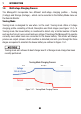
1 INTRODUCTION 1.5 Multi-stage Charging Process The Manager30 incorporates two different multi-stage charging profiles – Touring (3-stage) and Storage (8-stage) – which can be selected in the Battery Mode menu on the Remote Monitor. Touring Mode Touring mode is designed for use when ‘on the road’. Touring mode offers a 3-stage charging profile consisting of Boost, Absorption and Float stages (see Figure 1.5.1).
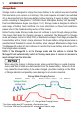
1 INTRODUCTION Storage Mode Storage mode is designed to charge the house battery to its optimal level and maintain that level while your caravan is in storage. This mode requires all loads to be switched off or disconnected from the house battery before charging. It uses a 8-stage* charging profile consisting of Desulphation*, Soft Start, Boost, Absorption, Battery Test, Equalise**, Float and Maintenance stages (see Figure 1.5.2).
1 INTRODUCTION IMPORTANT When The Manager30 is set to ‘Storage’ mode and no valid charging sources are connected, it will enter a ‘Sleep’ mode 30 seconds after the last user interaction. The sleep mode is designed to limit the amount of current drawn from the output battery by the system whilst in Storage mode and does this by switching the screen and all nonessential functions off.
2 INSTALLATION GUIDE 2.1 System Layout Battery Sensor Solar Panels Vehicle Battery (Not Supplied) (Not Supplied) To Loads (Not Supplied) House Battery DC - DC Power Source (Not Supplied) BMS1230 Remote Monitor 240VAC Mains Power Figure 2.1.1 - System Layout 2.2 Mounting Instructions This section describes how to mount the three major components of The Manager30: the Main Unit, the Remote Monitor and the Battery Sensor. Figure 2.2.
2 INSTALLATION GUIDE 2.2.1 Mounting the Main Unit Do NOT expose the Main Unit to rain, snow, spray or bilge water. For optimum operation, The Manager30 should be mounted where the temperature is nominally below 35°C and does not exceed a maximum of 60°C. The Manager30 must not be mounted in the vehicle engine bay. The Main Unit must not be installed in a location with any less than 10cm clearance at the top of the Main Unit, to allow for airflow across the heatsink fins.
2 INSTALLATION GUIDE 2.2.2 Mounting the Remote Monitor The Remote Monitor should be mounted inside the caravan or RV using the template provided on Page 36. It is acceptable however to mount the Remote Monitor in any convenient location, as long as it is protected from harsh environments. The Remote Monitor is connected to the main unit with the 5m CANBus cable. Figures 2.2.2.1 and 2.2.2.2 illustrate how to recess and wall mount the Remote Monitor unit, Figure 2.2.2.
2 INSTALLATION GUIDE Wall Mount 1 2 Use the template provided (Page 36) to mark the position and drill and cut the mounting holes into the wall. Attach the Back Plate to the wall using 4 suitably sized countersunk screws. 3 4 Feed the Remote Monitor cable through the hole and connect it to the Remote Monitor. Clip the Inner Assembly into the Back Plate. 5 6 Clip the Front Face to the Inner Assembly. Figure 2.2.2.2 - How to wall mount the Remote Monitor.
2 INSTALLATION GUIDE Removing the Remote Monitor 1 2 The locking tabs on the back of the Inner Assembly need to be unclipped from the Back Plate. The locking tabs can be accessed through holes on the top of the backing plate when installed. 3 4 Insert a flat-head screwdriver at a slight angle towards the front of the Remote Monitor and push back to depress the locking tabs. When the screwdriver is in a vertical position, gently push upwards on the bottom of the Remote Assembly to unlock tab.
2 INSTALLATION GUIDE 2.2.3 Mounting the Battery Sensor The length of cables on the Battery Sensor to connect to the Main Unit and the House Battery will dictate the allowable mounting distance from the battery. The Battery Sensor should be mounted to a solid surface using two suitably sized screws for attachment. Figure 2.2.3.1 illustrates how to mount the Battery Sensor. Figure 2.2.3.1 - Mounting the Battery Sensor 2.
2 INSTALLATION GUIDE 2.3.1 Input Wire Diameter Selection REDARC recommends the installer use cabling and connections between 8B&S and 6B&S automotive. REDARC recommends that the input wire be of the size outlined in Table 2.3.1. Distance from input vehicle battery to The Manager30 Recommended Cross Sectional Area (mm²) Recommended Diameter Equivalent ≤3m 8 8 B&S >3m 13 6 B&S Figure 2.3.1 - Recommended input cable size 2.3.
2 INSTALLATION GUIDE 2.4 The Manager30 Wiring Connections REDARC recommends that this unit be installed by a suitably qualified person. The AC power connection must be connected to an earthed socket outlet. Do not use The Manager30 AC input if the cord is damaged. Use of a non-genuine or damaged AC input cord may result in a risk of fire, electric shock, or injury to persons.
2 INSTALLATION GUIDE 2.4.3 Connecting the Battery Sensor Wire the Battery Sensor as shown in Figure 2.4.1.1 ensuring that the Battery Positive Lead connects to the house battery positive terminal. This lead measures voltage and temperature at the battery. The “BNEG” stud connects to the House Battery negative terminal and the “GND” stud connects to the vehicle common ground point. Connect the CANBus Connection cable to either of the main unit CANBus interfaces.
20 A single fuse and holder setup from the Fuse Kits available from REDARC. Part number FK40 (40A) or FK60 (60A). *1 The size of this fuse relates to the total current draw of all the loads connected to the House Battery, and should be rated slightly higher than this. REDARC recommend the use of MIDI Style Fuses. *2 Essential loads are loads which must be left on at all times, until the battery is flat.
2 INSTALLATION GUIDE 2.5 Batteries Working in the vicinity of a Lead-Acid battery is dangerous. Batteries generate explosive gases during normal operation. For this reason, it is of utmost importance that you follow the instructions each time you use the charger. Only use the Battery Charger for charging Standard Automotive Lead Acid, Calcium Content, GEL, AGM, SLI, Deep Cycle or Lithium Iron Phosphate type 12V batteries.
2 INSTALLATION GUIDE 2.6 MPPT Solar Regulator The Manager30 is designed for use with 12V solar panels. A minimum input voltage of 17.5V is required to start charging from a solar source. Once charging has started, the operating voltage range of the solar input can go as low as 9V and as high as 32V; outside of this range, charging will stop. The power output from solar panels varies depending on the amount of sunlight and the electrical load on the solar panel output.
3 USER GUIDE 3.1 Remote Monitor The Remote Monitor is designed to give you control of how the battery is being charged, as well as up-to-date house battery and charge information at any time during the charging process. You can check battery charge status, estimated charge time and State of Charge (SOC) per hour over a day and per day over a month. It also allows you to select charging profiles specific to the battery type and size.
3 USER GUIDE 3.3 Initial Setup When The Manager30 is first switched on the unit will prompt the user to enter a number of settings. It is important to enter these settings accurately as they directly affect the operation and performance of The Manager30. Set the Language: The first step required for initial setup is Language selection. Once entered the Language is set in memory and retained should power be lost and reconnected.
3 USER GUIDE 3.4 User Menu The Manager30 features a real time clock (time and date) function which needs to be setup when the power is first connected. Set the Time & Date Charging Status Screen N/A Battery Charge Screen The Manager30 monitors current in and out of the house battery, keeping track of the charge remaining. This screen displays the estimated state of charge of the house battery in percentage along with a bar graph.
3 USER GUIDE The Input Status screen displays a summary of the inputs to the system. The Solar input is the priority, providing as much usable input power as possible. If another source is present and the Solar input is not providing maximum (30A) input, the other source will attempt to make up the remaining allowable input power. This screen provides input voltage level as well as percentage (bar graph) of input power provided. Only two sources are used at any one time.
3 USER GUIDE 3.5 Settings Menu To access the Settings menu both the Up and Down buttons must be held for 2 seconds. This allows you to modify your Battery Setup, Remote Settings and some Advanced Settings, as well as providing a restore Factory Settings option and an About screen. The first screen in the Settings menu is the Battery Setup screen. The Battery Setup displays the selected battery settings for the battery under charge.
3 USER GUIDE The Remote Settings menu allows modification of the settings listed below. Edit Selected Setting Cycle through Settings Remote Settings Screen Cycle through Settings Each setting can be adjusted using the ‘Up’ and ‘Down’ controls. Confirm Setting Adjustment Adjust Setting (Up) Cancel Setting Adjustment Adjust Setting (Down) The Advanced Settings menu allow modification of settings relating to advanced operations of The Manager30 unit.
3 USER GUIDE The MaxCharge Current setting refers to the amount of current permitted by The Manager30 to charge the battery, up to a maximum of 30 Amps. Set Charging Current Screen R-Bus Diagnostics Screen Advanced Settings Screen Low SOC Alarm Screen If the Charging Current setting is set lower than 30 Amps the excess current will be used to supply the loads running from the battery under charge.
3 USER GUIDE The Load Disconnect setting will output a GROUND relay trigger signal based on a user set SOC or voltage level. Disconnect Trigger Screen Low Voltage Alarm Screen Advanced Settings Screen Set DC Input Trigger Screen The Disconnect Trigger setting can be set to Disconnect (Loads OFF), Connect (Loads ON) or to operate from either SOC or Voltage level triggers.
3 USER GUIDE Ignition selects Ignition Trigger, Auto is controlled by The Manager30, and 12V or 24V lock the unit to a 12V or 24V system. ON means the unit can trigger DC charging whenever there is a voltage between 9 - 32V on the DC Input wire. The default value is ‘Auto’. Confirm Setting Change Setting Cancel Setting Change Setting This screen is used by REDARC to identify problems with a The Manager30 setup and does not need to be accessed unless requested by REDARC Technicians.
3 USER GUIDE If The Manager30 detects a problem with the charging system that prevents it from continuing to charge the battery, it will alert you via a ‘Fault’ screen and an alarm buzzer, and will instantly terminate the charging cycle until the fault condition is cleared. The screen will give a brief description of the problem and will allow you to select either ‘Clear’ or ‘Ignore’. Both options will clear the fault screen.
3 USER GUIDE Faults CHARGER FAULT MESSAGE CAUSE ACTION Charger over current fault Return to supplier Unit over temperature fault.
3 USER GUIDE 3.8 Factory Settings The Manager30 is shipped with a number of settings already programmed into the unit. These settings are set to ensure that the charger will safely charge any battery and may not reflect the actual requirements for your battery type. It is important to review these settings and adjust as required.
3 USER GUIDE 3.9 Frequently Asked Questions Q I have damaged my Power Cable and need to replace it, do I have to buy a special kind of cable. A To ensure the correct operation of The Manager30, REDARC advise that if the supply cord is damaged it must be replaced by the genuine REDARC cord available from the manufacturer.
4 REMOTE DRILL TEMPLATE 36
THIS PAGE INTENTIONALLY LEFT BLANK 37
5 TWO YEAR PRODUCT WARRANTY Over the last three decades our company has established a reputation as the power conversion specialist. A 100% Australian-owned company, we have met the needs of customers in transport and other industries through exciting, innovative thinking.
Free technical assistance! For product and technical support contact your regional distributor, call our head office between 8:00am to 5:30pm Australian Central Standard Time, Monday to Friday or send an email using the regional specific details outlined below. Australia (and other Global regions) power@redarc.com.au www.redarc.com.au +61 8 8322 4848 New Zealand power@redarcelectronics.co.nz www.redarcelectronics.co.nz +64-9-222-1024 North America power@redarcelectronics.com www.redarcelectronics.