*Q7RE / PPH3RE SERIES 14 SEER Installation Instructions Single Package Heat Pump - Single Stage, R-410A IMPORTANT ATTENTION INSTALLERS: It is your responsibility to know this product better than your customer. This includes being able to install the product according to strict safety guidelines and instructing the customer on how to operate and maintain the equipment for the life of the product.
Table of Contents IMPORTANT SAFETY INFORMATION......................3 REQUIREMENTS & CODES......................................4 general information.........................................4 Before You Install this Unit........................................4 Locating the Heat Pump...........................................4 Minimum Clearances................................................5 Service Access Clearance:...................................5 Clearances to Combustibles:.........................
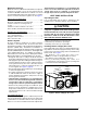
IMPORTANT SAFETY INFORMATION Please read all instructions before servicing this equipment. Pay attention to all safety warnings and any other special notes highlighted in the manual. Safety markings are used frequently throughout this manual to designate a degree or level of seriousness and should not be ignored. WARNING indicates a potentially hazardous situation that if not avoided, could result in personal injury or death.
REQUIREMENTS & CODES general information • All electrical wiring must be completed in accordance with local, state & national codes and regulations and with the National Electric Code (ANSI/NFPA 70) or in Canada the Canadian Electric Code Part 1 CSA C.22.1. • The installer must comply with all local codes and regulations which govern the installation of this type of equipment. Local codes and regulations take precedence over any recommendations contained in these instructions.
Minimum Clearances Minimum clearances MUST be maintained from adjacent structures to provide room for proper servicing and air circulation. DO NOT install unit in a confined or recessed area that will allow discharge air from the unit to re-circulate into the condenser air inlet, through the coil. See Figure 1. Service Access Clearance: Blower access panel side........................................... 24” Electrical compartment access panel side................
SINGLE DUCT APPLICATION MULTIPLE DUCT APPLICATION Figure 3. Typical Duct Applications Supply Duct 1. Assemble the collar by overlapping the two ends. NOTE: One end of the collar is slotted and the opposite end has two small holes. Position the end with small screw holes underneath the slotted end. 2. Fasten the collar ends with two self drilling sheet metal screws. 3.
Locating & Installing the Supply Damper(s) When locating the supply damper(s), carefully check floor joists and frame members that could interfere with the installation of the damper or flexible duct. Ideally, the damper (Figure 5) should be located in the bottom of the main duct, forward of center of the home, at least three feet from the nearest register. The round supply opening in the slanted side of the damper should face the side of the home where the heat pump is located. Figure 4.
Electrical Connections WARNING: To avoid electric shock, personal injury, or death, turn off the electric power at the disconnect or the main service panel before making any electrical connections. • Electrical connections must be in compliance with all applicable local codes and ordinances, and with the current revision of the National Electric Code (ANSI/NFPA 70). • For Canadian installations the electrical connections and grounding shall comply with the current Canadian Electrical Code (CSA C22.
Grounding WARNING: The unit cabinet must have an uninterrupted or unbroken electrical ground to minimize personal injury if an electrical fault should occur. Do not use gas piping as an electrical ground! This unit must be electrically grounded in accordance with local codes or, in the absence of local codes, with the National Electrical Code (ANSI/NFPA 70) or the CSA C22.1 Electrical Code. Use the grounding lug provided in the control box for grounding the unit.
Model Number 024K 030K 036K 042K 048K 060K External Static Pressure Drop (in WC) Motor Tap 0.1 0.2 0.3 0.4 0.5 0.6 0.7 0.
Startup & adjustments Pre-Start Checklist The following check list should be observed prior to starting the unit. √ Is the unit level? Unit should be level or slightly slanted toward the drain for proper condensate drainage. √ Is the unit installed with the proper clearances as listed on page 5? √ Is the wiring correct according to the wiring diagram and electrical codes? √ Are all the wiring connections tight? Check the condenser fan to make sure it turns freely.
• Inspect and clean or replace air filters at the beginning of each heating and cooling season, or more frequently if required. • Inspect the condensate drain and outdoor coil at the beginning of each cooling season. Remove any debris. Clean the outdoor coil and louvers as necessary using a mild detergent and water. Rinse thoroughly with water. • Inspect the electrical connections for tightness at the beginning of each heating and cooling season. Service as necessary.
figures & tables W Top View 1.75 Ø Electric Heater Power Supply L 1.125 Ø Power Supply 0.875 Ø Low Voltage Supply Side View H Control Access Panel 17.86 15.36 Blower Access Panel 10.10 5.5 3.2 B 18.01 12.13 Opening for 14" Diameter Return Duct Opening for 12" Diameter Supply Duct 3/4" NPT Drain Connection 1.38 A 3” 1" 3.2 5.29 Rear View 10.15 9.15 3.15 9.0 17.50 1” Model Number Length (L) Width (W) Height (H) A B 024K 49 35 30.2 35.02 2.48 030K 49 35 30.2 35.
Refrigerant Charging Tables - Cooling LEGEND NOTES: Shaded boxes indicate flooded conditions. Rated design values. The suction pressure will vary from design value if outdoor air flow, entering dry bulb, or entering wet bulb temperatures vary. 1. All pressures are listed psig and all temperatures in °F 2. Discharge temperatures greater than charted values indicate an undercharged system. 024K Series OUTDOOR TEMPERATURE (° F) Suct. Press.
LEGEND NOTES: Shaded boxes indicate flooded conditions. Rated design values. The suction pressure will vary from design value if outdoor air flow, entering dry bulb, or entering wet bulb temperatures vary. 1. All pressures are listed psig and all temperatures in °F 2. Discharge temperatures greater than charted values indicate an undercharged system. 036K Series OUTDOOR TEMPERATURE (° F) Suct. Press. 131 133 135 137 139 141 143 145 147 149 151 153 155 157 70 75 80 85 90 95 100 105 Liq. Dis.
LEGEND NOTES: Shaded boxes indicate flooded conditions. Rated design values. The suction pressure will vary from design value if outdoor air flow, entering dry bulb, or entering wet bulb temperatures vary. 1. All pressures are listed psig and all temperatures in °F 2. Discharge temperatures greater than charted values indicate an undercharged system. 048K Series (with restrictor) OUTDOOR TEMPERATURE (° F) Suct. Press.
Refrigerant Charging Tables - Heating LEGEND NOTE: Shaded boxes indicate flooded conditions. Rated design values. • All pressures are listed psig and all temperatures in °F 024K Series OUTDOOR TEMPERATURE (° F) Liq. Press. Dis. Temp. Suc. Press. Liq. Press. Dis. Temp. Suc. Press. Liq. Press. Dis. Temp. Suc. Press. Liq. Press. Dis. Temp. Suc. Press. Liq. Press. Dis. Temp. 60 Suc. Press. 50 Dis. Temp. 40 Liq. Press. 30 Suc. Press. 20 Dis. Temp. 10 Liq. Press. Suc.
LEGEND NOTE: Shaded boxes indicate flooded conditions. Rated design values. • All pressures are listed psig and all temperatures in °F 042K Series OUTDOOR TEMPERATURE (°. F) 84 324 Dis. Temp. 118 Liq. Press. 283 Suc. Press. 68 138 Dis. Temp. 112 303 310 317 122 120 174 170 165 382 389 396 201 195 189 403 183 156 152 127 128 129 130 131 132 410 417 177 170 147 133 424 164 Liq. Press. 276 282 289 296 60 Suc. Press.
LEGEND: FIELD WIRING LOW VOLTAGE HIGH VOLTAGE RED 3 AMP FUSE RED HPS HGBP COIL SENSOR 240V G R C O HP2 HP1 LP2 LP1 Y1 IN R O C Y1 FAN1 E GREEN FAN2 CCH2 CCH1 GREY BLACK RED BROWN WHITE Y2 W2 NC RVS BLACK BLACK BLACK RELAY NO BLACK CCH VIOLET VIOLET 1 3 WHITE BLUE ORANGE OUTDOOR THERMOSTAT (ON SELECT MODELS) W2 OUT RV2 RV1 W2 IN Y2 IN COIL#1 DEFROST TEMP CONTROL BOARD HOT1 HOT2(24V COM) Y1 OUT SEE NOTE 5 Y2 OUT LPS OUTDOOR TEMP AMB SENSOR 24V COM TRANSFORMER R C
LEGEND: FIELD WIRING LOW VOLTAGE HIGH VOLTAGE RED 3 AMP FUSE RED HPS HGBP COIL SENSOR 240V G FAN1 Y1 R C O HP2 HP1 LP2 LP1 O C Y1 IN R E GREEN Y2 W2 RVS BLACK CCH VIOLET VIOLET 1 3 WHITE BLUE ORANGE T2 T1 L2 L1 3, 3.
Figure 11. W.D.
Typical Wiring (Field Supplied) for 1-Stage Cool, 1 Stage Electric Heat White wire not present when optional thermostat is used INDOOR TERMINAL THERMOSTAT DEFROST BOARD R C G O BROWN ORANGE W2 Y1 Y2 E Outdoor Thermostat (Factory Option) W2 IN 1 2 3 4 5 6 7 8 9 ACCESSORY HEAT PLUG W2 OUT Typical Wiring (Field Supplied) for 1-Stage Cool, 2 Stage Electric Heat White wire not present when optional thermostat is used INDOOR TERMINAL THERMOSTAT DEFROST BOARD R C G O W2 Y1 Y2 E Outdoor Thermost
INSTALLATION / PERFORMANCE CHECKLIST REFRIGERATION SYSTEM INSTALLATION ADDRESS: CITY_________________________ STATE_________________ UNIT MODEL #_________________________________________ UNIT SERIAL #_________________________________________ Unit Installed Minimum clearances per Figure 1 (page 4)? YES YES NO Stage-1 Liquid Pressure (high side)_________________________ Stage-1 Suction Pressure (low side)_________________________ NO ELECTRICAL SYSTEM INSTALLER NAME: CITY________________________ Was