
Revolve RPH Installation Manual


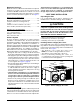


Table Of Contents
- IMPORTANT SAFETY INFORMATION
- REQUIREMENTS & CODES
- general information
- HEAT PUMP INSTALLATION
- Electrical Connections
- Startup & adjustments
- Unit MAINTENANCE
- figures & tables
- INSTALLATION / PERFORMANCE CHECKLIST

4
GENERAL INFORMATION
Single packaged heat pumps are ready for easy and
immediate installation and can be readily connected
into the high static duct system of a home. This unit is
completely assembled, wired, and run tested at the factory.
This heat pump is designed for outdoor installation
only. The only connections needed for installation are the
supply and return ducts, the line voltage, and thermostat
wiring. Use of components other than those specified may
invalidate AHRI Certification, Code Agency Listing, and
limited warranty on the air conditioner.
Before You Install this Unit
√ The cooling load of the area to be conditioned must be
calculated and a system of the proper capacity selected.
It is recommended that the area to be conditioned be
completely insulated and vapor sealed.
√ Check the electrical supply and verify the power supply
is adequate for unit operation. If there is any question
concerning the power supply, contact the local power
company.
√ All units are securely packed at the time of shipment and
upon arrival should be carefully inspected for damage
prior to installing the equipment at the job site. Verify
coil fins are straight. If necessary, comb fins to remove
flattened or bent fins. Claims for damage should be filed
immediately with the carrier.
√ Please consult your dealer for maintenance information
and availability of maintenance contracts. Please read
all instructions before installing the unit.
Locating the Heat Pump
• Surveythejobsitetodeterminethebestlocationfor
mounting the outdoor unit. Select a solid, level position,
preferably on a concrete slab, slightly above the grade
level, and parallel to the home. If possible, select a site
for the unit that is as close as possible to the proposed
return grille location. DO NOT PLACE UNIT UNDER
THE HOME.
• The unit should be located with consideration of
minimizing the length of the supply and return ducts
with no sharp radius bends. If practical, place the heat
pump and its ducts in an area where they will be shaded
from the afternoon sun, when the heat load is greatest.
• Consideration should also be given to availability of
electric power, service access, noise, and shade.
• Overhead obstructions, poorly ventilated areas, and
areas subject to accumulation of debris should be
avoided. The hot condenser air must be discharged up
and away from the home, and if possible, in a direction
with the prevailing wind. Do not place the unit in a confined
space. See Figure 8 (page 13) for unit dimensions.
• Sufcientclearanceforunobstructedairowthroughthe
outdoor coil must be maintained in order to achieve rated
performance. For minimum clearances to obstructions,
see Figure 1.
REQUIREMENTS & CODES
• Allelectricalwiringmustbecompletedinaccordance
with local, state & national codes and regulations and
with the National Electric Code (ANSI/NFPA 70) or in
Canada the Canadian Electric Code Part 1 CSA C.22.1.
• The installer must comply with all local codes and
regulations which govern the installation of this type
of equipment. Local codes and regulations take
precedence over any recommendations contained in
these instructions. Consult local building codes and the
National Electrical Code (ANSI CI) for special installation
requirements.
• Air Ducts must be installed in accordance with the
standards of the National Fire Protection Association
“Standards for Installation of Air Conditioning and
Ventilation Systems” (NFPA 90A), “Standard for
Installation of Residence Type Warm Air Heating and Air
Conditioning Systems” (NFPA 90B), these instructions,
and all applicable local codes.
• ConsultTable 2 (page 10), and the rating plate for
the proper circulating air flow and temperature rise. It is
important that the duct system be designed to provide
the correct flow rates and external pressure rise. An
improperly designed duct system can result in nuisance
shutdowns, and comfort or noise issues.
• Thisunitisdesignedforoutdoorinstallationsonlyand
should be positioned as described in Locating the Heat
Pump.
12"
12"
24"
TOP OF UNIT
TO BE
UNOBSTRUCTED
0"
Figure 1. Minimum Unit Clearances