as82 of of Re:system M10 Modular Audio Multiroom System Dominating Entertainment. Revox of Switzerland.
Re:system M10 1
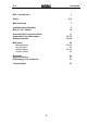
M10 Re:system M10 – Introduction 3 Safety 4-6 M10 Unit Views 7 Installation and Assembly M10 in a 19” Cabinet 8 10 Overview: M10 Connection Panel Connection Panel Description Ethernet Interface 11 12-15 16-19 M10 Setup Ethernet Setup Source Setup Remote Setup Version Control 20 20-24 25 25-29 30 Guarantee Scope of delivery Disposing of your old device 31 31 31 Technical Data 32 2
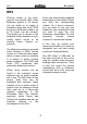
Re:system M10 M10 Working quietly in the background, the modular M10 Audio Multiroom System in 19” format, can be relied on to supply a complete house with music. With the plug-in Multiroom module, up to 32 rooms can be included. This allows you to choose in the individual rooms between a highquality stereo sound or an exciting Home Cinema experience. Once new technologies establish themselves on the market, Revox can offer the corresponding module.
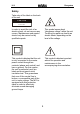
Re:system M10 Safety Take note of the label on the back of the unit. CAUTION R I S K OF E L E C T R IC S HO C K D O NO T O P E N In order to avoid the risk of an electric shock, do not remove any covers. Maintenance and repairs should only be carried out by qualified experts. This symbol warns about “dangerous voltage” within the unit. Touching live parts can lead to an electric shock, depending on the level of the voltage.
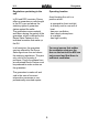
Re:system M10 Installation and operation Safety measures Please check the unit and accessories for any signs of transit damage after unpacking. Read the operation manual through carefully before starting to use the unit. Keep the manual for later reference. Unusual operation Unplug the unit from the mains immediately in the event of any unusual noises or odours. Have the unit checked by your dealer without delay.
Re:system M10 Operating location Regulations pertaining to the unit Avoid locating the unit in a position which: In EU and EEC countries, Revox offers a guarantee on units bought in the EU, over and above the statutory rights of guarantee claims against the seller. The guarantee covers material and labour during the period of the guarantee, which is defined by the Revox Sales Partners in the individual countries that make up the EU.
Re:system M10 M10 Unit views M10 Front view M10 Rear view A2 A1 8 7 6 5 Note: Slots A1 and A2 may only be populated with second generation modules that have been developed since the start of 2008.
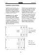
Re:system M10 Installation and assembly The M10 is an 19“ build-in unit, which was principally conceived for insertion into a 19” cabinet. Thanks to the integrated unit feet, however, it is possible to position it outside of a 19” cabinet. The M10 can be installed with the plug-in slots directed to the front or the back. See figure on Page 9. Depending on the cabling strategy, the plug-in module cables can be fed in at the front of the unit or concealed at the back.
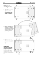
Re:system M10 Modifying the retaining bracket 1. All 6 Allen screws (3 mm) are removed from both sides of the M10 2. Now, the retaining bracket is moved from the front to the back in the corresponding position. ! 3. All 6 screws are then screwed back in as shown in the figure. Please note Also the two outside screws, which don’t hold the retaining bracket to the M10, must be screwed back in.
Re:system M10 M10 Installation in a 19“ cabinet Sectional view of a 19”cabinet with installed M10 A) M10 retaining bracket forward-spaced. B) M10 retaining bracket inserted.
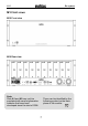
Re:system M10 Overview: M10 Connection panel M10 – Front side (Partial view) M10 – Rear (Partial view) On/ Off switch USB-B connection for PC Mains connection with fuse RS232, only for firmware updates Operational display LED, green/blue SD card slot, software update Error display LED, red M-Link for Revox interfaces LAN Ethernet connection 3.
Re:system M10 Description: M10 Connection panel On/Off switch The M10 can be completely separated from the mains supply with the on/off switch. This is recommended if the Revox Multiroom System is not going to be used for a few weeks during a vacation, for example. The M10 must remain switched on during normal operation so that access to the Multiroom System from the connected rooms is available at all times.
Re:system M10 LAN Ethernet connection A connection to an Ethernet LAN can be established through the RJ45 socket. The Ethernet interface is configured manually during the M10 setup. DHCP functionality is not supported. LED red – flashing quickly A) Temperature is too high There is overheating in the M10 housing. The maximum permitted temperature value has been exceeded even though the fan is active. The two LEDs integrated in the RJ45 socket indicate the status of the data connection.
Re:system M10 Installing the USB driver USB-B connection for PC As the Revox USB driver is not yet present on the Windows operating system, you will be asked to make the corresponding driver available. Revox recommends not taking the Windows option to “search for Driver” but to tell Windows which folder the driver is in manually. Following the installation of MScope, you will find the correct driver for the M10 in the folder C:\ Programme\ Revox\ M-Scope\ USB Driver under the name M51usb.
Re:system M10 RS232 interface M-Link for Revox interfaces The serial interface is used exclusively for configuring the M10 and for installing new firmware, if the USB or Ethernet interface is blocked. It is not possible to operate third-party devices with it, nor is it possible to connect external RS232 interfaces, e.g. EIB data interface. The M-Link is a Revox interface, which various Revox interfaces can be connected to, e.g. M200 Domotic interface, M201 IR interface, etc.
Re:system M10 Ethernet interface The Ethernet interface enables the M10 to be integrated into a LAN. In this way, each computer that is also integrated in the LAN can access the Revox system, using the corresponding Revox control software. As well as operation through the Revox service programs, the M10 also offers the option to influence the Revox Multiroom System and/ or to let feedback messages be directed specifically into a visualisation, through the use of a primary (domestic) control system.
Re:system M10 M-Text Protocol (UDP) M233 Display panel As well as understanding the Revox internal M-Link protocol, the M10 Ethernet interface with the software version 1.10 or higher also understands the clear text commands (M-Text protocol) in ASCII format. This makes it possible to integrate the Revox system in a domestic control system, e.g. with the GIRA Home Server.
Re:system M10 Connection DHCP is not supported by the M10. This means that all the necessary settings for a fault-free integration of the M10 in an Ethernet system must be made manually. You will find details about this in the Chapter M10 Setup. Point-to-Point A Crossover cable is used if the M10 is connected directly to a PC. Distribution with Router A Patch cable (1:1) is used of the two devices are connected over a router. You will find an overview of a possible Ethernet network on the next page.
Re:system M10 Functional plan The IP addresses shown above are only examples and must be modified to meet the needs of the particular installation.
Re:system M10 M10 Setup Ethernet Setup A PC or a Notebook is always needed for the initial configuration of the M10, which is connected to the M10 using the RS232 interface or the USB socket . The Ethernet setup is reached through the Ethernet softkey. All the settings that are needed for the integration of the M10 in a LAN are done on 2 configuration pages. The first menu page shows you a Client List of all devices that are currently accessing the M10.
Re:system M10 CLIENT LIST Page TCP/IP The CLIENT LIST shows all devices that are currently accessing the M10. Up to 10 clients can have parallel access. The base settings for the Ethernet access are set through the two TCP/IP pages. If no client is logged on, four zeros appear in the corresponding line. The setting is made by selecting the corresponding address block with the softkeys, which is then shown in square brackets 192.[168].0.6 In the example below, three clients are accessing the M10.
Re:system M10 IP Address IP Subnet Mask ➮ [ ➮ [ ] ] The 4 blocks of the IP Subnet that the M10 should have are set using the two Mask softkeys. The 4 blocks of the IP address that the M10 should have are set using the two Address softkeys. In a network of DHCP-enabled LAN Clients, you must always ensure that these are not given the M10’s IP. Default Gateway ➮ [ ] The 4 blocks of the Default Gateway that defines the external access in the Internet are set using the two Gateway softkeys.
Re:system M10 Page TCP/IP UDP/IP Address ➮ [ ] The second page in the UDP/IP setup is responsible for all the UDP settings. Here, all the relevant settings for the UDP address and port are made, as well as the selection of the MText modes. UDP/IP address: Here you can enter the target address, if the UDP packet should only be sent to one specific recipient. The new settings are confirmed with the Apply softkey. Otherwise the previous setting is retained. UDP/IP Port Using the setting 255.255.255.
Re:system M10 Source - Menu M-Text Mode Using the Source softkey, you can access the setup menu for the plug-in module that is currently playing in Zone 1 and there you can make the required settings for this module. The audio signal from this source can also be heard through the integrated speaker or the headphone socket. The selection of the M-Text mode is only relevant if an UDP port is used as a port. If, on the other hand, the TCP/IP port 5524 is used, the M-Text mode setting is irrelevant.
Re:system M10 Remote Function Zone-dependant Remote menu The modularity of the M10 requires a flexible usage of operating units, as the M10 can be equipped with a wide range of modules. An operating unit can, for example, be the M218 Wallmounted keypad or the M208 Remote control. The Revox Multiroom system has 4 Multiroom zones where different music can be heard independently of each other.
Re:system M10 Calling Remote Select zone Select the Remote softkey in the Main menu. To start with, you select the (Multiroom) zone with the Zone softkeys. We recommend starting with Zone 1 as then all further zones take the Zone 1 settings as default values. As shown in the following graphic, the Remote menu is divided into the areas: - Zone - Button - Source The same Remote buttons are available in each zone.
Re:system M10 Select button variable Select source Using the Button softkeys, you select the button variable that you want to assign to a specific audio source at the M10. You can toggle backwards and forwards through a loop of the four button variables with Button+ and Button-. The remote button Tuner symbolises, for example, the Tuner button on the M218 Wallmounted keypad. Using the two Source softkeys, an audio source is assigned to the previously selected button variable, e.g.
Re:system M10 If, on the other hand, the Remote button should activate a different source in one or more zones, you switch zones with the Zone button. In the newly selected zone, another audio source can now be assigned to the same Remote button. of the SAT module is activated with the button variable Tuner. Note: If several modules of the same type, e.g. Tuner are installed in the M10 these can no longer be differentiated though their names as, for example, all Tuner modules register with FM-Tuner.
Re:system M10 Disable variable This function allows you to Disable the remote button. This makes the audio source no longer addressable through the operating unit or remote control. To do this, select the required Remote button through the Zone/ Button combination and press the Disable softkey. The Store softkey then appears that you need to press to confirm your change. If you don’t press Store, the original setting is retained.
Re:system M10 Software version The Version function displays the current version number for each module along with the plug-in slot that it occupies. The first column with the $ sign shows the module’s plug-in slot with the hexadecimal numbers $1 to $F. Select the Version softkey in the Setup main menu. The second column defines the corresponding module. The Master Tuner module, for example, is represented as FMT-1. The last column shows the software version of the corresponding module.
Re:system M10 Scope of delivery Disposing of your old devices Your product has been manufactured from highquality materials and components that can be recycled. If this symbol of a crossed-out, wheeled rubbish container is on the product, this means that it is covered by the EU Directive 2002/96/EG.
Re:system M10 Technical data Serial data transfer: RS232 SUB D 9-pin 1:1 cabling (socket) Audio connections Headphone output: max. 1 W / min. 16 Ω Dimensions Width x Depth : 443 x 310 mm (without retaining bracket/ unit feet) 17.44 x 12.2 inch Height : 171 mm (corresponds to 4 RU) 6,73 inch Weight 11.0 kg / 24.
Re:system M10 GERMANY Revox GmbH, Am Krebsgraben 15, D-78048 VS-Villingen, Germany Phone +49 7721 8704 0, Fax +49 7721 8704 29 info@revox.de, www.revox.de SWITZERLAND Revox Schweiz AG, Wehntalerstrasse 190, CH-8105 Regensdorf, Switzerland Phone +41 44 871 66 11, Fax +41 44 871 66 19 info@revox.ch, www.revox.ch Central Service Revox GmbH, Am Krebsgraben 15, D-78048 VS-Villingen, Germany Phone +49 7721 8704 43, Fax +49 7721 8704 49 info@revox.de 33 Re:system M10 Operating Instructions / Part.No.: 10.30.