
Technical data

I/O Module Re:source
6
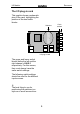
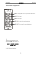
The I/O plug-in card
This graphic shows a schematic
plan of the card, highlighting the
position of the two switch
blocks:
The upper and lower switch
blocks define the left and the
right channel of AUX-1
respectively. For this reason,
they must always have the
same switch settings.
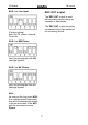
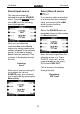
The following switch settings
should be used for the different
input sources.
L
The best thing to use for
positioning the switches is a
stylus or a small screw driver.
Switches
I/O plug-in card
Cinch
sockets