
Operation Manual


PAGE 4
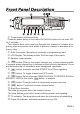
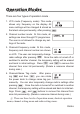
q Power button & Selector Knob:
Press the power button to turn radio ON, hold the button to turn radio OFF
for 3 seconds.
Turn selector knob clock wisely go through next channel or increase a fre-
quency step and counter clock wisely to previous channel or decrease a fre-
quency step.
w RJ45 Connector: Microphone connector or programming lead.
e LCD Display: The display include 16x2 two rows of dot matrix
r Speaker: Inner speaker
t button: Press it then press relevant key, or keep pressing within
2 seconds press relevant key to achieve multiple shortcut operations. Press
and hold more than 2 seconds to enter background operations.
y button: transmits selected DTMF/2-Tone/5Tone signalling
u button: To toggle channel and VFO mode.
i button: Select scan type FREQ/CH SCAN ,CTCSS/DCS SCAN or
PRIORITY WATCH then press button to execute.
o button: Press the button to temporarily monitor receiving.
a button: Press once to enter channel setup.
s Busy/Scan Indicator:
The lamp glows green when the channel is busy.
The lamp fl ashes green which mean matching carrier and signaling.
d TX indicator: The lamp glows red when the transceiver is transmitting.
f Power On Indicator: indicates transceiver is turn ON.
Front Panel Description
C
A
L
L
V/M
SCAN
S
O
/
C
E
N
T
E
R
FUNC