Form I-ADF (Version A.3) Obsoletes Form I-ADF (Version A.2) Installation Indoor or Outdoor Gas, Direct-Fired, Makeup Air/Heating Systems, Model ADF and Model ADFH Applies to: Model ADF ! WARNING: FIRE OR EXPLOSION HAZARD Failure to follow safety warnings exactly could result in serious injury, death, or property damage.
Table of Contents 1.0 General.......................................................... 2 6.0 Mechanical.................................................... 9 2.0 Location........................................................ 3 7.0 Electrical and Wiring................................. 19 1.1 Hazard Labels and Notices..............................2 1.2 General Description ........................................3 1.3 Warranty............................................................3 1.
1.2 General Description The information in this manual applies to Model ADF and Model ADFH in Sizes 300, 500, 700 and 1200. Both Model ADF and ADFH are direct-fired makeup air heating systems. Model ADFH is designed with a high discharge air temperature. These systems consist of a direct-fired, gas-fueled burner and a draw-through blower housed in a weatherized cabinet. The systems may be installed either indoors or outdoors and are available for use with either natural or propane gas.
3.0 Uncrating and Preparation 3.1 Uncrating and Inspecting 3.2 Preparing for Installation Shipped-Separate Components Check for any damage that may have been incurred during shipment. If damage is found, document the damage with the carrier and immediately contact an authorized Reznor® distributor. Check the gas specifications and electrical voltage (system rating plate is in the control compartment) to be sure that they agree with the utilities at the installation site.
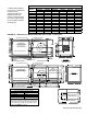
Dimensions (mm) - Illustration in FIGURE 1A (Sizes 300 & 500) ** Models ADFH 300/500 have a motor compartment required for high temperature discharge. Models 300/500 with optional vertical discharge have same cabinet length as the standard horizontal discharge unit.
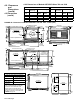
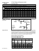
4.2.2 Dimensions of Models ADF/ADFH Sizes 700 and 1200 4.0. Clearances and Dimensions (cont'd) Dimensions (inches) - FIGURE 1B Horizontal Vertical Discharge Discharge ModADF/ ADF/ ADF els ADFH ADFH Size 700/1200 700 1200 A 92-1/8 117-1/32 117-1/32 B 72-1/8 69-7/8 C 13-13/16 16-1/16 4.
5. Mounting Mounting is the responsibility of the installer. Depending on the building and its use, determine whether or not additional field measures should be taken to reduce the effect of blower vibration and/or noise. Determining the need for and installing vibration isolation is the responsibility of the installer. When selecting a location for an outdoor installation, position the unit so that the air inlet will NOT be facing into the prevailing wind.
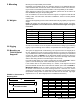
5.0 Mounting (cont'd) FIGURE 3 - Cross Support Mounting Requirements 5.3 Mounting on Field-Supplied Supports (cont'd) 5.4 Mounting on a Roof Curb CAUTION: Before assembly, re-check to be sure that the correct curb has been ordered. Be sure that the curb selected matches the unit ordered. Verify the dimensions of the curb received with the curb dimension table, FIGURE 4.
Model ADF300 ADF500 Discharge Horizontal or Vertical Roof Curb Dimensions (inches) - FIGURE 4 A 84-9/16 84-9/16 B 29-13/16 43-9/16 C* 80-13/16 80-13/16 D* 26-1/16 39-13/16 Roof Curb Dimensions (mm) - FIGURE 4 A 2148 2148 B 757 1106 C* 2053 2053 D* 662 1011 *C and D are roof opening dimensions.
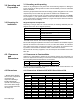
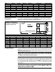
6.0 Mechanical (cont'd) 6.1 Gas Piping and Pressures (cont'd) Gas Supply Piping Capacity of Piping Cubic Feet per Hour based on 0.3" w.c. Pressure Drop Specific Gravity for Natural Gas -- 0.6 (Natural Gas -- 1000 BTU/Cubic Ft) Specific Gravity for Propane Gas -- 1.
Pilot Supply Pressure These systems are designed to operate on a natural gas pilot supply pressure of 3.5" w.c. or a propane gas pilot supply pressure of 6" w.c. Measure both operating pressure and pilot supply pressure with the blowers in operation. Manifold Pressure Manifold pressure is defined as the gas pressure as measured at the burner pressure tap. Measure manifold gas pressure with the blowers operating. Minimum gas pressure at the burner is typically 4.3" w.c. for natural gas or typically 1.
6.0 Mechanical (cont'd) 6.2 Unit Inlet Air (cont'd) 6.2.1 Screened Outside Air Hood without Filters (cont'd) Installation Instructions (Refer to Air Hood Assembly Drawing in FIGURE 8B. All screw ends except those across the bottom should be inside the air hood.) To avoid possible damage, it is recommended that the outside air hood be installed after the unit has been placed on the roof. The air hood should be installed before the heater is operated.
Instructions for installing pre-assembled outside air hood with filters: FIGURE 9A - Optional Screened Outside Air Hood with Filters 1. On the inlet air end of the system, remove the row of factory-installed screws attaching the cabinet top. 2. Tip the assembled air hood slightly and slide the top flange underneath the cabinet top. The air hood must be between the cabinet top and the end panel. Slide the side flanges into the slots between the corner posts and the end panel. (See FIGURE 9A). 3.
6.0 Mechanical (cont'd) 6.2 Unit Inlet Air (cont'd) 6.2.3 Indoor Filter Cabinet (cont'd) 6.2.4 Evaporative Cooling Module Options AS4 and AS8 FIGURE 11A - Factoryinstalled Evaporative Cooling Module Option on Models ADF/ADFH 300 and 500 3. Re-insert all of the screws across the top of the cabinet. 4. The filter cabinet should be resting on the factory-installed support angle across the bottom of the cabinet.
FIGURE 12 - Optional Evaporative Cooling Module on an ADF/ ADFH 700 or 1200. Assembled module is shipped separately for field installation. an adjustable base, and the transition ductwork between the cooling module and the cabinet. Complete installation instructions including dimensions are packaged with the evaporative cooling module package. Included in the cooling module installation booklet is a preparation checklist.
6.0 Mechanical (cont'd) 6.2 Unit Inlet Air (cont'd) 6.2.4 Evaporative Cooling Module Options AS4 and AS8 (cont'd) Supply and Drain Water Connections (cont'd) All Cooling Modules - A manual water shutoff should be installed upstream of the inlet, at a convenient non-freezing location, to allow the water supply to be turned on and off. If necessary, install a bleed line between the manual valve and the cooling module inlet to allow drainage of the line between the shutoff valve and the cooling module.
Filling & Adjusting the Water Level in the Reservoir Float and Pump Control System -- Turn on the water supply. Check for good flow. When the float valve (FIGURE 13) shuts off the water supply, measure the water depth. The depth of the water should be approximately 3". It may be necessary to adjust the float valve to obtain the proper water level or to free the float valve from obstructions.
6.0 Mechanical (cont'd) 6.3 Supply Air Discharge 6.3.2 Two-Position Discharge Dampers, Option AQ4 FIGURE 19 - Model ADF with Horizontal, Two-Position Discharge Damper, Option AQ4 Form I-ADF, Page 18 6.3.1 Distribution of Makeup Air Makeup air can be introduced to the building either through distribution ducts or through controlled pressurization with little or no ductwork. Makeup air should be introduced and maintained using the lowest possible air velocity.
6.4 Blowers, Drives, and Blower Motors FIGURE 20 - Belt Tension Check belt tension. Proper belt tension is important to the long life of the belt and motor. A loose belt will cause wear and slippage. Too much tension will cause excessive motor and blower bearing wear. If adjustment is required, adjust belt tension by means of the adjusting screw on the motor base until the belt can be depressed 1/2" or 3/4" (FIGURE 20). Be sure the belt is aligned in the pulleys.
7.0 Electrical and Wiring (cont'd) 7.2 Supply Wiring (cont'd) CAUTION: Supply voltage and 24-volt control wiring cannot be installed in the same conduit. Maxitrol systems will be adversely affected if control wiring is in conduit with supply voltage wiring. If required, field-supplied wiring between any Maxitrol components must be completed with shielded wiring.
Dirty Filter Light (on the Remote Console) When a console with a dirty filter indicator is selected, the remote console includes a fourth light (dirty filter indicator light). The light is activated by an adjustable, singlepole/normally open differential pressure switch that senses air pressure across the filter bank. There are field-installation procedures that must be done for proper operation of the dirty filter indicator light.
8.0 Controls (cont'd) Control used for Outside Air Cutoff and Discharge Low Temperature Limit (Freezestat) perature of the incoming outside air. The outside air cutoff (high ambient control) is factory set at 60°F (adjustable 25-250°F). The burner reacts differently depending on the entering air temperature and the setting on this control.
Check disconnect switch to be sure that it is tightly secured against the cabinet. If disconnect is fusible, check that fuses are installed. If fuses are not installed, insert correct fuses. Verify continuity of fuses. 6. Open the hinged gas/electrical control compartment door -Close all manual gas valves. Open hinged electrical panel cover. Check all wiring and wiring connections on gas controls and electrical components.
9.0 Commisoning and Startup (cont'd) 9.2 Startup Diagnostic Lights 1. Prepare system for startup testing -Attach a slope gauge (0 to 1.0" scale) to the tubing connections in the control compartment. The two connections are located just left of the electrical box. Remove the caps on the 1/8" NPT test connections and attach the slope gauge. (The recommended method for attaching the slope gauge is to use field-supplied 1/8" female NPT x 1/4" OD barbed hose connections.
If the slope gauge reading is greater than -.25" (such as -.10" w.c.), adjust the drive to increase the blower speed. (1) Turn disconnect switch OFF. (2) For systems with smaller than 7-1/2 HP motor (a) Loosen belt tension and remove belt. (b) Loosen the set screw on the side of the pulley away from the motor. (c) Turn adjustable half of the pulley inward to increase blower speed. One turn of the pulley will change speed 8 to 10%. (d) Tighten the set screw on the flat portion of the pulley shaft.
9.0 Commissioning and Startup (cont'd) 9.2 Startup (cont'd) 6. Check pilot pressure and operation -To check pilot gas pressure, connect a "U"-tube manometer to the pressure tap on the downstream side of the pilot solenoid valve. Put BOTH blower and burner switches in TEST position. Turn ON disconnect switch. After blower reaches speed, all lights should be lit except "Pilot Valve" and "Main Valve". Turn on the gas supply.
Limits Based on Eight -Hour Exposure and a 5-Day Week (Guide Only) Substance............... Percent.... PPM Substance............... Percent.... PPM Acetaldehyde........... .001............... 10 Formaldehyde.......... .000025...... 0.25 Carbon Dioxide........ .250........... 2500 Nitrogen Dioxide...... .0001............... 1 Carbon Monoxide.... .001............... 10 Sulphur Dioxide....... .00005.......... 0.5 Note: At 100°F rise the CO2 concentration will be in the order of 2500 ppm.
INSTALLATION RECORD - to be completed by the installer: Installer: Name ________________________________________________________ Company ________________________________________________________ Address ________________________________________________________ ________________________________________________________ ________________________________________________________ Phone _________________________________ Distributor (company from which the unit was purchased): Company _______________