
Installation

Mfg No. 131134, Page 1
APPLIES TO: Models F, FE, B, BE with a Single-Stage
Gas Valve
OPTION CQ3
LOW AMBIENT FAN
CONTROL RELAY
INSTALLATION FORM RZ-NA I-F/B-LA
Obsoletes Form RGM 434/436-LA (Version .2)
®
Description
Option CQ3, Low Ambient Fan Control Relay Kit, is designed
to prevent false cycling of the fan/blower on the unit heaters
installed in areas with ambient temperature of less than 40°F.
When the room temperature is below 40°F, the standard tem-
perature-activated fan control may be cooled enough by the ini-
tial airflow to cause the fan/blower to shut off. Since the burner
is still lit, the fan control will be reheated causing the fan/blower
to cycle on and off.
The optional time delay relay is actuated electrically, indepen-
dent of room temperature or heat exchanger temperature. On
heater start-ups, the time delay relay will start the fan/blower in
about 45 seconds. On heater shutdown, the time delay will con-
tinue to operate the fan/blower for about 60 seconds to cool the
heat exchanger. If the ambient temperature in the room is in-
creased during heater operation, the fan control will act to keep
the fan/blower on longer, until the heat exchanger is adequately
cooled.
IMPORTANT: Do not remove the fan control from the heater
circuit. The fan control is a safety device.
The Option Package (P/N 113779) includes:
Qty P/N Description
1 114007 Time Delay Relay Assembly (consisting of
a time delay relay, Thermodisc #305055,
P/N 97479, and four wire assemblies)
2 82485 Screws, #4 x 3/8" long (for attaching relay
assembly)
1 16354 Wire Nut
1 98117 Open/Closed Bushings (required for units
with lower horizontal partition; not required
on units with cable holders - See Figure 1)
Installation Instructions
Installation should be done by a qualified agency in accordance
with these instructions and in compliance with all codes and
requirements of authorities having jurisdiction.
1. If the heater is installed, turn off the gas and electric power.
2. Remove the outer side panel on the left side of the heater (left
when facing the back of the heater), exposing the inner side
panel and wiring.
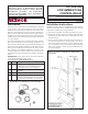
3. On the vertical partition of the inner side panel, there are
three locations with holes for mounting relays. The relay in
this kit is designed to attach at the top set of holes (See Fig-
ure 1). Position the relay on the electrical compartment side
of the vertical partition. Attach, using the smaller holes and
the screws provided.
Figure 1 - Location for Mounting Low Ambient Fan
Control Relay
WARNING: Improper installation, adjustment,
alteration, service or maintenance can cause
property damage, injury or death. Read the
installation, operation, and maintenance
instructions thoroughly before installing or
servicing this equipment.
Option CQ3, Low Ambient Fan Control Relay Kit