Form I-F/B (Version C) Obsoletes Form I-F/B (Version B) Installation / Operation / Maintenance Applies to: Model F and Model B Gas-Fired, Gravity-Vented Unit Heaters M TY N P R T UA E LI ST O D TY SY RA U CT WA R Q Model B C U S TO M E R CQS STA RT-UP AG C S PROC CY E EN VERGE S N N O Model F ! WARNING: FIRE OR EXPLOSION HAZARD Failure to follow safety warnings exactly could result in serious injury, death, or property damage.
TABLE OF CONTENTS 1. General........................................................ 2-3 7. Electrical Supply and Wiring................. 23-29 1.1 Hazard Labels and Notices............................. 2 7.1 General........................................................... 23 1.2 General Installation Information..................... 3 7.2 Supply Voltage and Wiring............................ 23 1.3 Warranty........................................................... 3 7.3 Control Wiring.............
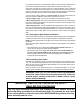
1.2 General Installation Information Installation should be done by a qualified agency in accordance with the instructions in this manual and in compliance with all codes and requirements of authorities having jurisdiction. The instructions in this manual apply only to Model F and Model B unit heaters. 1.3 Warranty Refer to the limited warranty form in the "Literature Bag" WARRANTY: Warranty is void if...... a.
2. Unit Heater Location (cont'd) 2.1 General (cont'd) When units are located in the center of the space to be heated, the air should be discharged toward the exposed walls. In large areas, units should be located to discharge air along exposed walls with extra units provided to discharge air in toward the center of the area.
ter, stepdown transformer, and blower/filter cabinet. After becoming familiar with the instructions, assemble and install the options that are required for your heater. Unless the crate bottom has been removed for option installation, leave it attached until after the heater has been suspended. If the crate bottom has been removed, the bottom of the heater must be supported with plywood or appropriately placed boards. Without adequate support, the bottom access panel could be damaged.
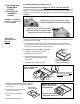
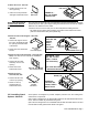
3. Uncrating and Preparation (cont'd) 3.2 Preparing for Installation (cont'd) 3.2.2 Assembling Vent Outlet (cont'd) Vent Outlet Instructions for Sizes 25, 50, 75, 100, 165 and 200 The heater in these sizes is shipped with the vent outlet in the horizontal position and requires no further field preparation. However, if a vertical vent outlet connection is needed, reverse the positions of the flat cover plate and the flue collar assembly. See FIGURE 2.
4. Attach the Cover - Size 125 • Position the flat cover over the top opening • Fasten on the top and back with eight sheetmetal screws Vent Outlet Instructions for Sizes 250, 300 and 400 FIGURE 3C Size 125, STEP 4 - Attach Cover The vent outlet for Sizes 250, 300, and 400 always requires field assembly. The three sheetmetal pieces and a parts bag including the instructions and screws are shipped attached to the drafthood of the heater. 1.
3. Uncrating and Preparation (cont'd) 3.2 Preparing for Installation (cont'd) 4. Clearances and Dimensions 3.2.3 Installing Guard Options - Model B (cont'd) FIGURE 5 - Optional Guards Optional Blower Inlet Guard Installed Optional Belt Guard Installed (NOTE: Unit illustrated is not a Model B. The belt guard is the same but is on the other side of a Model B heater.) 4.
4.
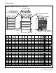
4. Clearances and Dimensions (cont'd) 4.
Dimensions - mm FD Size A B CH D E 25 766 344 1102 799 148 50 766 344 1270 799 75 766 395 1270 799 100 766 446 1270 125 813 592 1207 165 1020 516 200 1020 250 1020 300 400 L G AC H I J K AB 367 1559 483 102 Rnd 261 406 13 13 148 367 1559 483 102 Rnd 261 406 13 13 148 367 1559 483 127 Oval 267 406 13 13 799 148 367 1559 483 152 Oval 328 406 13 13 799 148 367 1674 456 178 Oval 367 406 13 13 1549 913 124 495 1934 5
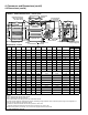
5. Hanging the Heater (cont'd) 5.2 Lifting and Suspending (cont'd) FIGURE 8 - Suspension Point WARNING: Unit must be level for proper operation. Do not place or add additional weight to the suspended heater. See Hazard Levels, page 2. 5.2.1 Optional, FieldInstalled Hanger Kits Add nut to lock to inner panels. NOTE: Do not lock to cover panels. This may prevent the outer side panel from being removable for future service. WARNING: Suspend the heater only from the threaded hanger brackets.
includes two hanger bracket assemblies, four swivel hanger connector assemblies and four lock washers. 4) Four-Point Swivel Connectors - Option CK10 (See FIGURE 10) FIGURE 10 - Four-Point Suspension with Swivel Connections (Applies to both fan and blower models) This option package is used on a heater that is already equipped with four-point suspension to adapt it for suspension from four 1", threaded, stationary pipes. The kit includes four swivel hanger connector assemblies and four lock washers.
6. Mechanical (cont'd) 6.1 Gas Piping and Pressures (cont'd) All piping must be in accordance with requirements outlined in the National Fuel Gas Code ANSI/Z223.1a (latest edition), published by the American Gas Association or CAN/CSA-B149.1 and B149.2, published by the Canadian Gas Association (See Paragraph 1.4). Gas supply piping installation should conform with good practice and with local codes.
6.1.2 Manifold or Orifice Pressure Settings WARNING: Manifold gas pressure must never exceed 3.5" w.c. for natural gas and 10" w.c. for propane. Instructions on How to Check Valve Outlet (Manifold) Pressure (can only be done after heater is installed): CAUTION: DO NOT bottom out the gas valve regulator adjusting screw. This can result in unregulated manifold pressure causing excess overfire and heat exchanger failure. Measuring manifold gas pressure cannot be done until the heater is in operation.
6. Mechanical (cont'd) 6.1 Gas Piping and Pressures (cont'd) 6.1.2 Manifold or Orifice Pressure Settings (cont'd) 3. With the manual valve positioned to prevent flow to the main burners, connect a manometer to the 1/8” pipe outlet pressure tap in the valve. Use a fluid-filled manometer that is readable to the nearest tenth of an inch w.c. 4. Remove the cap from the pressure adjusting screw and adjust the manifold pressure to the pressure setting selected from the table.
is recommended. Where it is necessary to run the vent pipe through an exterior wall of combustible materials, a suitable thimble must be used. The vent pipe shall have a clearance of at least six inches (152mm) from combustible materials, or as is specified by the double-wall vent pipe manufacturer. 4. With the outlet on the heater in the horizontal position, it is recommended that a 12-18" (305-457mm) piece of straight pipe be connected to the flue collar before installing an elbow.
6. Mechanical (cont'd) 6.2 Venting (cont'd) 6.2.2 Venting Requirements (cont'd) 9. If the unit heater is installed in a space served by a large exhaust fan, be sure that the exhaust fan does not affect the operation of the heater or the satisfactory venting of its products of combustion. If a negative pressure exists, as evidenced by a downdraft, a factory-designed mechanical motor driven venter (Option CA) should be installed.
6.2.3 Vent Control Damper, Option AV7 NOTE: A gravity-vented unit heater manufactured after August 7, 2008, MUST be installed with either an automatically controlled motorized vent damper (Option AV7) or power venting (Option CA). 6.2.4 Optional Power Venting - Option CA NOTE: Do not install an Option CA venter on a heater equipped with voltage option AK11, 220-240/1/50 Hertz. FIGURE 18 - Venter Assembly and Adapter 6.
6. Mechanical 6.4 Unit Discharge 6.4.1 Vertical Louvers, Option CD1 - Apply to F and B FIGURE 20 - Optional Vertical Louvers CAUTION: To avoid getting burned, adjust louvers prior to heater operation. If louvers need re-adjusting after start-up, wear protective gloves. 6.4.2 Downturn Air Nozzles, Options CD2, CD3, CD4, and CD5 - Applies to Model F and B as listed All fan type Model F heaters are factory equipped with horizontal louvers.
6.4.4 Polytube Adapter - Options CD6, CD8, and CD11 - applies to Model B only The polytube adapter option is designed to adapt this blower-type heater for use with polytube ductwork. The use of polytubes for air distribution is common in greenhouse applications and some industrial applications. A polytube distribution system delivers warm air to a specific area, reducing the need for complete area heating.
6. Mechanical (cont'd) 6.5.1 Fan Operation - Model F 6.5.2 Belt Tension and Blower Operation Model B Blower Model Sizes 25-100 are standardly equipped with a direct drive motor; an optional belt drive motor is available on Sizes 50-100. Blower Model Sizes 125-400 have an adjustable belt drive motor. As part of the Check/Test/Start (Paragraph 9), check the belt for proper tension and check that the setscrews are tight to the shaft. Proper belt tension is important to the long life of the belt and motor.
4. Cut the crimped cap from the end of the wire that you intend to use and strip the insulation. 5. Disconnect the factory-wired connection and re-wire, using the newly stripped wire. 6. Put a wire nut on the end of the blower motor wire that was disconnected. 7. Replace the heater side panel and turn on the gas and the electric. Blower Model Sizes 50-400 with Belt Drive The belt drive on these units is equipped with an adjustable pulley which permits adjustment of the blower speed.
7. Electrical Supply and Wiring (cont'd) 7.2 Supply Voltage and Wiring (cont'd) and 25). This switch may be used to disconnect the power when servicing the heater other than in the supply junction box. WARNINGS: On a heater with a unit disconnect switch (Option AI-1), when the power is turned off at the unit-mounted switch, the supply lead in the electrical supply junction box (FIGURE 24) remains energized.
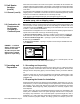
When factory-installed options require two-stage thermostat control, the heater is equipped with a SP-ST relay and a four-screw terminal connector strip (See FIGURE 27). If your heater requires field installation of the four-screw terminal strip and the relay, follow the instructions packaged with the relay or thermostat option. FIGURE 28 illustrates the wiring and the connections required for an optional field-installed fan relay.
7. Electrical Supply and Wiring (cont'd) 7.4 Typical Wiring Diagrams FIGURE 30 - Fan-type, Gravity-Vented, Model F Sizes 25-400 with Intermittent Spark Pilot, Single Stage Heating, Natural or Propane NOTES - THE FOLLOWING CONTROLS ARE FIELD INSTALLED OPTIONS: THERMOSTAT AND S/W SWITCH - THE FOLLOWING CONTROLS ARE FACTORY INSTALLED OPTIONS: NONE - DOTTED WIRING INSTALLED BY OTHERS.
FIGURE 31 - Blower-type, Gravity-Vented, Model B Sizes 25-100 with Intermittent Spark Pilot, Single Stage Heating, Natural or Propane, Direct Drive NOTES OPERATING SEQUENCE - THE FOLLOWING CONTROLS ARE FIELD INSTALLED OPTIONS: THERMOSTAT, S/W SWITCH AND BLOWER RELAY - THE FOLLOWING CONTROLS ARE FACTORY INSTALLED OPTIONS: NONE - DOTTED WIRING INSTALLED BY OTHERS.
7. Electrical Supply and Wiring (cont'd) 7.4 Typical Wiring Diagrams (cont'd) FIGURE 32 - Blower-type, Gravity-Vented, Model B Sizes 50-250 with Intermittent Spark Pilot, Single Stage Heating, Natural or Propane, Belt Drive OPERATING SEQUENCE - SET THERMOSTAT AT LOWEST SETTING. - TURN ON MAIN AND PILOT MANUAL GAS VALVES. - TURN ON POWER TO UNIT. - SET THERMOSTAT AT DESIRED TEMPERATURE. - THERMOSTAT CALLS FOR HEAT FIRING UNIT AT FULL RATE AFTER PILOT PROVING SEQUENCE.
FIGURE 33 - Blower-type, Gravity-Vented, Model B Sizes 165-400 with Intermittent Spark Pilot, Single-stage Heating, Natural or Propane, Belt Drive, Blower Motor Contactor (Note: Motor contactor is standard on Sizes 300 and 400; Optional on other sizes.
8. Controls 8.1 Fan Control 1. A fan control provides the following: (a) Delay of fan or blower operation to prevent the discharge of cold air. (b) Fan or blower operation as long as the unit is hot. 2. The fan control provides additional safety by keeping the fan or blower in operation in the event that the gas valve fails to close when the thermostat is satisfied. 3.
NOTES: Natural gas units manufactured prior to 9/2007 may have Option AH2, which is a spark ignited intermittent safety pilot system with recycling pilot without lockout. Units manufactured prior to 8/2008 may have a matchlit pilot. 8.5 Pilot and Ignition Systems The pilot on Model F and B unit heaters is a spark ignited intermittent safety pilot system with lockout (Option AH3).
9. Commissioning and Start-Up 9.1 Check the installation prior to start-up: Check suspension. Unit must be secure and level. Blower Model - Check to be sure that all shipping supports have been removed. Rubber feet must be on the motor bracket bolts. See Paragraph 3.2. Check clearances from combustibles. Requirements are shown in Paragraph 4.1. Check vent system to be sure that it is installed according to the instructions in Paragraph 6.2. Check piping for leaks and proper gas line pressure.
10. Maintenance and Service NOTE: Use only factory-authorized replacement parts. 10.1 Maintenance Schedule 10.2 Maintenance Procedures FIGURE 35 - Gas Valve SingleStage Valve 1/8" INLET Pressure Tap NOTE: Operational pressure settings and instructions for checking pressure settings are in Paragraph 6.1. WARNING: If you turn off the power supply, turn off the gas. See Hazard Levels, page 2. This unit will operate with a minimum of maintenance.
10. MAINTENANCE AND SERVICE (cont'd) 10.2.2 Burner Rack Removal CAUTION: Eye protection is recommended. FIGURE 36 - Bottom Access Panel Open These unit heaters have a convenient bottom access panel. The pilot is attainable with the bottom panel open. With the access panel removed, the burner rack assembly will hinge down for removal. Use the following step-by-step instructions for removal of the bottom access panel and the complete burner rack assembly.
FIGURE 40 - Burner Orifices Burner Orifices FIGURE 39 Burner Rack Hinged Down Burner Assembly Support Brackets FIGURE 41 - Burner Rack Completely Removed FIGURE 42 Individual Burners Individual burners may be cleaned using air pressure. Use an air nozzle to blow out scale and dust accumulation from the burner ports. Alternately, blow through burner ports and venturi. Use a fine wire to dislodge any stubborn particles. Do not use anything that might change the port size. d.
10. Maintenance and Service (cont'd) FIGURE 44 - Pilot Burner Spark Gap (Spark Pilot) 10.2 Maintenance Procedures (cont'd) 10.2.3 Pilot and Ignition Systems (cont'd) CAUTION: Due to high voltage on pilot spark wire and pilot electrode, do not touch when energized. See Hazard Levels, page 2. The ignition controller of the optional intermittent electronic ignition pilot system is visibly located on the back of the heater. (See FIGURE 45.
Fan Models: Follow these instructions for replacement of the fan guard, fan motor or fan blades. FIGURE 47 Proper Position of the Fan Blade on the Motor Shaft 1. If the heater is installed, turn off the gas and disconnect the electric power. 2. Remove the left outer side panel (left when facing the rear of the unit). Disconnect the fan motor wires. 3.
10. Maintenance and Service (cont'd) 10.2 Maintenance Procedures (cont'd) 10.2.10 Fan, Limit, & ECO Controls (cont'd) Instructions for replacing fan or limit control and ECO device: Limit Control 1. Turn off the electric power and shut off the gas supply. 2. Remove the outer left side panel left when facing the back of the unit). Fan Control Remove the access panel. 3. Remove defective controls. Install new controls in the same mounting holes. Use only factory-authorized replacement parts. ECO Device 4.
TROUBLE No heat (Heater Operating) PROBABLE CAUSE 1. Incorrect manifold pressure or orifices. 2. Cycling on limit control. 3. Improper thermostat location or adjustment. Cold air delivered 1. Fan control improperly wired On Start-up 2. Defective fan control. During Operation 3. Incorrect manifold pressure. Motor will not run 1. Circuit open. 2. Fan control inoperative. 3. Defective motor or capacitor. Motor turns on 1. Fan control improperly wired. and off while 2. Defective fan control.
INSTALLATION RECORD - to be completed by the installer: Installer: Name ________________________________________________________ Company ________________________________________________________ Address ________________________________________________________ ________________________________________________________ ________________________________________________________ Phone _________________________________ Distributor (company from which the unit was purchased): Company _______________