
Installation Manual Owner manual


Form I-F/B, P/N 98126 R21, Page 15
6.1.2 Manifold or
Orice Pressure
Settings
Measuring manifold gas pressure cannot be done until the heater is in operation. It is
included in the steps of the "Check-Test-Start" procedure in Paragraph 9. The following
warnings and instructions apply.
CAUTION: DO NOT
bottom out the gas
valve regulator
adjusting screw.
This can result
in unregulated
manifold pressure
causing excess
overre and heat
exchanger failure.
WARNING:
Manifold gas
pressure must
never exceed 3.5"
w.c. for natural gas
and 10" w.c. for
propane.
For Natural Gas: When the heater leaves the factory, the combination gas valve is set
so that the outlet gas pressure of a single-stage valve or high re of a two-stage valve
is regulated to 3.5" w.c. Low re on a two-stage valve is set to 0.9" w.c. Inlet supply
pressure to the valve for natural gas must be a minimum of 5" w.c. or as noted on the
rating plate and a maximum of 14" w.c.
For Propane: When the heater leaves the factory, the combination gas valve is set so
that the outlet gas pressure of a single-stage valve or high re of a two-stage valve is
regulated to 10" w.c. Low re on a two-stage valve is set to 3.8" w.c. Inlet supply pres-
sure to the valve for propane gas must be a minimum of 11" w.c. and a maximum of
14" w.c.
Before attempting to measure or adjust valve outlet (manifold) gas pressure, the inlet
supply pressure must be within the specied range both when the heater is in opera-
tion and on standby. Incorrect inlet pressure could cause excessive manifold gas pres-
sure immediately or at some future time. If natural gas supply pressure is too high,
install a regulator in the supply line before it reaches the heater. If natural gas supply
pressure is too low, contact your gas supplier.
Instructions on How
to Check Valve Outlet
(Manifold) Pressure
(can only be done after
heater is installed):
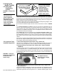
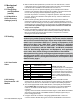
1) With the manual valve positioned to prevent ow to the main burners, connect a
manometer to the 1/8" pipe outlet pressure tap in the valve. NOTE: A manometer
(uid-lled gauge) is recommended rather than a spring type gauge due to the
difculty of maintaining calibration of a spring type gauge.
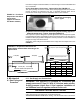
2) Open the valve and operate the heater. Measure the outlet pressure of the gas
valve. To measure low stage pressure on units equipped with a two-stage valve,
disconnect the wire from the "HI" terminal on the valve. (Be sure to reconnect the
wire.)
Normally adjustments should not be necessary to the factory preset regulator.
(For high altitude settings, see below.) If adjustment is necessary, remove the
cap from the adjustment screw(s). Set pressure to correct settings by turning the
regulator screw IN (clockwise) to increase pressure. Turn regulator screw OUT
(counterclockwise) to decrease pressure.
Derating by Valve Outlet (Manifold) Pressure Adjustment for High
Altitude Operation
If the heater is being installed above 2000 ft (610M) and it was determined in Para-
graph 3.2.1 that derating by valve outlet pressure adjustment is permissible, follow the
instructions that follow.
Instructions for Derating a Heater by Adjusting Valve Outlet Pressure
(The heater MUST have a single-stage gas valve and MUST be factory-
equipped for sea level operation.)
1. Check the rating plate to be certain that the heater is equipped for sea level
operation. Do not attempt to derate by valve outlet pressure adjustment if
the heater is factory equipped for high altitude. Do not attempt to adjust
manifold pressure on heaters equipped with two stage gas valves.
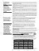
2. Determine the required valve outlet (manifold) pressure for the elevation where the
heater will be operating. If unsure of the elevation, contact the local gas supplier.
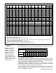
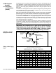
High Fire Valve Outlet (Manifold) Pressure by Elevation
Altitude Natural Gas Propane
Feet Meters (inches W.C.) (inches W.C.)
0- 2000 0-610 3.5 10.0
2001-3000 611-915 2.8 7.7
3001-4000 916-1220 2.5 7.1
4001-5000 1221-1525 2.3 6.4
5001-6000 1526-1830 2.1 5.8
6001-7000 1831-2135 1.9 5.2
7001-8000 2136-2440 1.7 4.6
8001-9000 2441-2745 1.5 4.1