
Installation Manual Owner manual


Form I-F/B, P/N 98126 R21, Page 7
Vent Outlet Instructions
for Sizes 250, 300 and
400
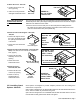
1. Remove the two center screws (one on each side) that are holding the three
ue outlet pieces in place during shipping. Use these screws and the 24 screws
(#10x1/2" sheetmetal screws) in the plastic bag.
FIGURE 3C -
Size 125, STEP 4
- Attach Cover
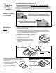
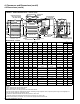
3. Attach the Flue Collar Assembly - Sizes 250, 300,
400 (If vent outlet is to be vertical; see Installation
Note, page 5.)
• Position the ue collar
assembly over the rear
opening
• Fasten with seven
sheetmetal screws
4. Attach the Cover -
Sizes 250, 300, 400
• Position the at cover
over the top opening
• Fasten on the top
and back with ten
sheetmetal screws
4. Attach the Cover - Size 125
• Position the at cover over
the top opening
• Fasten on the top and back
with eight sheetmetal screws
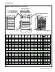
FIGURE 4A -
Sizes 250, 300,
and 400,
STEP 2 -
Attach
Flue Collar
Support
FIGURE 4B - Sizes
250, 300, and 400,
STEP 3 - Attach
Flue Collar Assy
The vent outlet for Sizes 250, 300, and 400 always requires eld assembly. The three
sheetmetal pieces and a parts bag including the instructions and screws are shipped
attached to the drafthood of the heater.
2. Attach the Flue Collar Support - Sizes 250,
300, 400
• Position the support around
the hole in the drafthood with
the opening toward the back
of the heater
• Fasten with nine sheetmetal
screws
FIGURE 4C -
Sizes 250, 300,
and 400, STEP 4
- Attach Cover
3.2.3 Installing Guard
Options - Model B
Guard options are designed to provide complete protection from the rotating drive
and/or blower components.
Option CD12 is designed for use with Model B Sizes 25-100 with standard direct drive
motor. This kit includes only the blower inlet guard.
Option CD10 is designed for use on Model B Sizes 50-400 with a belt driven motor and
includes both the belt guard and the blower inlet guard.