
Installation Manual Owner manual


Form I-F/B, P/N 98126 R21, Page 8
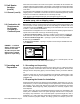
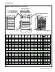
Notes:
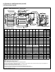
* Measure Top Clearance
as illustrated.
** When supplied with optional downturn nozzle, bottom clearance is 42"
(1067mm). For service purposes, on standard units, bottom clearance
exceeding minimum (12" or 305mm) is not required but may be desirable.
*** For service purposes only, rear must have 24" (610mm) clearance.
Model Required Clearances
Type Size Top *
Flue
Connector
Sides Bottom** Rear***
Fan
(Model F)
25 - 125
2" 6" 18" 12" 24"
51mm 152mm 457mm 305mm 610mm
165 - 400
6" 6" 18" 12" 24"
152mm 152mm 457mm 305mm 610mm
Blower
(Model B)
25 - 400
6" 6" 18" 12" 24"
152mm 152mm 457mm 305mm 610mm
All fuel-burning equipment must be supplied with the air that enters into the combus-
tion process and is then vented to the outdoors. Sufcient air must enter the equipment
location to replace that exhausted through the heater vent system. In the past, the
inltration of outside air assumed in heat loss calculations (one air change per hour)
was assumed to be sufcient. However, current construction methods using more insu-
lation, vapor barriers, tighter tting and gasketed doors and windows or weather-strip-
ping, and mechanical exhaust fans may now require the introduction of outside air
through wall openings or ducts.
The requirements for combustion and ventilation air depend upon whether the unit
is located in a conned or unconned space. An "unconned space" is dened as a
space whose volume is not less than 50 cubic feet per 1000 BTUH of the installed
appliance. Under all conditions, enough air must be provided to ensure there will
not be a negative pressure condition within the equipment room or space. For specic
requirements for conned space installation, see Paragraph 2.2.
4. Clearances and
Dimensions
4.1 Clearances
Units must be installed so that the following clearances are provided for combustion air
space, service and inspection, and for proper spacing from combustible construction.
Clearance to combustibles is dened as the minimum distance from the heater to a
surface or object that is necessary to ensure that a surface temperature of 90°F above
the surrounding ambient temperature is not exceeded.
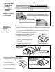
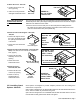
FIGURE 5 - Optional Guards
Optional Belt
Guard Installed
(NOTE: Unit illustrated
is not a Model B. The
belt guard is the same
but is on the other side
of a Model B heater.)
Optional
Blower
Inlet
Guard
Installed
3. Uncrating and
Preparation
(cont'd)
3.2 Preparing for
Installation
(cont'd)
3.2.3 Installing Guard Options - Model B (cont'd)