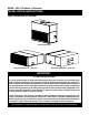
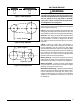
B5SM - 090 / 120 Series, A Revision Installation Instructions Light Commercial Air Handler Vertical Application Horizontal Application - Rear View Horizontal Application - Front View IMPORTANT ATTENTION INSTALLERS: It is your responsibility to know this product better than your customer. This includes being able to install the product according to strict safety guidelines and instructing the customer on how to operate and maintain the equipment for the life of the product.
Important Safety Information........................2 General Information...........................................3 Before You Install this Unit..........................................3 Locating the Air Handler.............................................4 Field Connections for Electrical Power Supply...........4 Air Ducts.....................................................................4 Unconditioned Spaces............................................4 Acoustical Duct Work...........................
WARNING: Improper installation, service, adjustment, or maintenance may cause explosion, fire, electrical shock or other hazardous conditions which may result in personal injury or property damage. Unless otherwise noted in these instructions, only factory authorized kits or accessories may be used with this product. WARNING: Unless otherwise noted in these instructions, only factory authorized kits or accessories may be used with or when modifying this product.
Locating the Air Handler • Survey the job site to determine the best location for mounting the unit. • Overhead obstructions, poorly ventilated areas, and areas subject to accumulation of debris should be avoided. • Consideration should be given to availability of electric power, service access, noise, and shade.
Connecting Refrigerant Tubing WARNING: NITROGEN HEALTH 1 FLAMMABILITY 0 REACTIVITY 0 0 Minimal Hazard 1 Slight Hazard Evaporator Coils are factory shipped with a nitrogen charge. Avoid direct face exposure or contact with valve when gas is escaping. Always ensure adequate ventilation is present during the depressurization process. Any uncertainties should be addressed before proceeding.
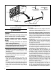
FILTER BRACKET LOCATION BRACKET CONFIGURATION FOR 1” FILTER APPLICATIONS (FACTORY SETTING) BRACKET CONFIGURATION FOR 2” FILTER APPLICATIONS FILTERS “Z” BRACKET “L” BRACKET REMOVE 4 SCREWS FROM FILTER RACK FRAME REMOVE 4 SCREWS SECURING “Z” BRACKET AND “L” BRACKET Figure 1. Converting from 1” Filter to 2” Filter Applications ELECTRICAL WIRING WARNING: ELECTRICAL SHOCK, FIRE OR EXPLOSION HAZARD Failure to follow safety warnings exactly could result in serious injury or property damage.
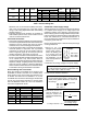
Model Phase Hertz Voltage -090Ja 3 60 208-230/460 -120Ja 3 60 208-230/460 -090Ka & -120Ka 1 60 208-230 Blower Motor Hp FLA SFA MCA MOP Unit Configuration 1 3.2-3.0/1.5 3.5-3.3/1.7 4.4-4.2/2.2 15 Factory Std. 1.5 4.4-4.2/2.1 5.0-4.6/2.3 6.3-5.8/2.9 15 w/ MSD kit 1.5 4.4-4.2/2.1 5.0-4.6/2.3 6.3-5.8/2.9 15 Factory Std. 2 6.0-5.8/2.9 6.7-6.4/3.2 8.4-8.0/4.0 15 w/ MSD kit 2 11.3 - 10.0 11.3 - 11.0 14.2 - 13.8 25 - 20 Factory Std.
The amount of phase imbalance (1.32%) is satisfactory since the amount is lower than the maximum allowable 2%. Please contact your local electric utility company if your voltage imbalance is more than 2%. Grounding WARNING: The unit cabinet must have an uninterrupted or unbroken electrical ground to minimize personal injury if an electrical fault should occur.
UNIT MAINTENANCE WARNING: Figure 2. V-Belt Alignment Never perform maintenance on energized or rotating equipment. Always disconnect electrical power and allow all rotating equipment to stop before servicing the unit. Failure to do so may result in personal injury, loss of limb, or death from electrical shock or entanglement in moving parts. The maintenance information listed below should be performed in accordance with the Maintenance Schedule shown in Figure 9 (page 16).
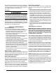
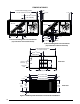
Figures & Tables 3/4" Field Installed Hanging Rods 47 5/8" Center to Center 1 1/4" 2 7/32" 23 13/16" CL of Unit 1" CL of Gravity Electrical Connections Electrical Connections Air Flow Air Flow 13 5/8" 15 9/16" 6 3/4" 4 3/4" 15 11/16" 8 3/16" 5 11/16" 4 3/8" 17 11/16" 7 1/2 Ton Unit Refrigerant Line Connections 4 3/16" 17 13/16" (Top View Shown with Doors Removed) 10 Ton Unit Refrigerant Line Connections (Top View Shown with Doors Removed) Field Installed Hanging Rods 57" Center to Center
18 13/16" Supply Duct 19 3/8" 22 1/16" 16 1/4" Electrical Knock-outs Top View 27 3/8"Cabinet Depth (without Filter Rack) 60 1/4"Cabinet Width 19 3/8" 18 13/16"Supply Duct Opening 16 1/4" Supply Duct Opening 22 1/16" 9 1/8" Electrical Connections Electrical Knockout for Optional Economizer 53 1/4" Cabinet Height 2 25 1/16" Filter Rack Frame 23" Return Duct Opening Condensate Drain 5 1/16" 53" Return Duct Opening 57" Filter Rack Frame Front View 29 5/16"Depth (with Filter Rack) Side View
Blower Performance Tables This equipment is equipped with a belt driven blower assembly in order to accommodate a large variety of duct configurations and airflow selections. The blower has been factory inspected for proper alignment, operation and rotational direction. For a more detailed explanation of belt driven blower drives and the operation of their components please refer to any of the installation instructions listed below for the high static drive kits.
B5SM-090Ka Factory Standard: 2Hp Blower Performance Chart External Unit Operation Static @ 230V (in-Wg) 0.1 0.2 0.3 0.4 0.5 0.6 0.7 0.8 0.9 1.0 CFM RPM kW CFM RPM kW CFM RPM kW CFM RPM kW CFM RPM kW CFM RPM kW CFM RPM kW CFM RPM kW CFM RPM kW CFM RPM kW ‡ Indicates Factory Sheave Setting Adjustable Motor Sheave Setting Fully Closed 1/2 Turn Open 1 Turn Open 1.5 Turns Open 2 Turns Open 3.5 Turns Open 4 Turns Open 4.5 Turns Open ‡ 5 Turns Open 3599 592 0.91 3450 3657 637 1.
B5SM-120Ka Factory Standard: 2Hp Blower Performance Chart External Unit Operation Fully Static @ 230V Closed (in-Wg) 0.1 0.2 0.3 0.4 0.5 0.6 0.7 0.8 0.9 1.0 1.1 1.2 CFM RPM kW CFM RPM kW CFM RPM kW CFM RPM kW CFM RPM kW CFM RPM kW CFM RPM kW CFM RPM kW CFM RPM kW CFM RPM kW CFM RPM kW CFM RPM kW ‡ Indicates Factory Sheave Setting Adjustable Motor Sheave Setting 2.5 Turns Open 3 Turns Open 3.5 Turns Open ‡ 4 Turns Open 4.5 Turns Open 5 Turns Open 4777 818 2.01 4624 820 1.93 4668 796 1.
B5SM-090Ja Factory Standard: 1Hp Blower Performance Chart External Operating Unit @ 230 or Fully Static 460 Volts Closed (in-Wg) 0.1 0.2 0.3 0.4 0.5 0.6 0.7 0.8 0.9 1.0 CFM RPM kW CFM RPM kW CFM RPM kW CFM RPM kW CFM RPM kW CFM RPM kW CFM RPM kW CFM RPM kW CFM RPM kW CFM RPM kW ‡ Indicates Factory Sheave Setting Adjustable Motor Sheave Setting 1/2 Turn Open 3660 711 1.07 3405 713 0.99 1 Turn Open 1.5 Turns Open 2 Turns Open 2.5 Turns Open 3 Turns Open ‡ 3.5 Turns Open 4 Turns Open 4.
B5SM-120Ja Factory Standard: 1.5Hp Blower Performance Chart External Operating Unit @ 230 or Static 460 Volts (in-Wg) 0.1 0.2 0.3 0.4 0.5 0.6 0.7 0.8 0.9 1.0 CFM RPM kW CFM RPM kW CFM RPM kW CFM RPM kW CFM RPM kW CFM RPM kW CFM RPM kW CFM RPM kW CFM RPM kW CFM RPM kW ‡ Indicates Factory Sheave Setting Adjustable Motor Sheave Setting 1 Turn Open 1.5 Turns Open ‡ 2 Turns Open 2.5 Turns Open 3 Turns Open 3.5 Turns Open 4 Turns Open 4.
electrical information WIRING DIAGRAM B5SM Series 7.5/10T Air Handler Systems Electrical Configurations Elec. Code J K GENERAL NOTES: 1. Disconnect all power before servicing. 2. If wiring must be replaced, use only 105˚C copper wire of the same gauge. 3. For economizer application, refer to wiring instructions in economizer installation instructions for connection details. THREE PHASE ONLY NOTES: 1. Three phase units are factory wired for 460V/60Hz operation. 2.
NOTE: C &W2 to be connected to electric heat. TO FIELD SUPPLIED DISCONNECT GND SINGLE STAGE HEAT/COOL THERMOSTAT L1 R W C G Y L2 OPTIONAL L3 BLOWER MOTOR FREEZESTAT GREEN BROWN C Y R G C W2 W1 O Y R BLACK See Note BLACK TERMINAL BOARD AIR HANDLER SECTION OUTDOOR SECTION SINGLE STAGE HEAT/COOL THERMOSTAT- NO ECONOMIZER NOTES: 1. C & W2 to be connected to electric heat. 2. Remove BLACK wire from air handler low voltage terminal board Y terminal and connect to YELLOW wire from economizer. 3.
NOTES: 1. Jumper between W2 and E is required. 2. C &W2 to be connected to electric heat. TO FIELD SUPPLIED DISCONNECT GND SINGLE STAGE HEAT PUMP THERMOSTAT L1 R O W2 E C G Y B L2 L3 NOTE 1 BLOWER MOTER FREEZESTAT BROWN C W2 O R Y OUTDOOR SECTION G C GREEN BLACK W2 O R Y W1 NOTE 2 BLACK TERMINAL BOARD AIR HANDLER SECTION TYPICAL HEAT PUMP THERMOSTAT CONNECTION (NO ECONOMIZER) NOTES: 1. Jumper between W2 and E is required. 2. C & W2 to be connected to electric heat. 3.
Installers Name: _________________________________ Date Installed: _________________________________ PERFORMANCE SCHEDULE MAINTENANCE TASK W M SA DATE PERFORMED A AIR FILTERS Inspect, clean, or replace as required. X CONDENSATE DRAIN(S) & PAN Clean condensate drain pan X Inspect the flow of condensate through the drain lines. Clean or correct problems as necessary. X BLOWER ASSEMBLY Inspect the fan belt for wear, alignment, & proper tension. Replace or adjust as required.