
User Manual

5
Connecting Refrigerant Tubing
WARNING:
Evaporator Coils are factory shipped with a
nitrogen charge. Avoid direct face exposure or
contact with valve when gas is escaping. Always
ensure adequate ventilation is present during
the depressurization process. Any uncertainties
should be addressed before proceeding.
• When connecting refrigerant linesets together, it is
recommendedthatdrynitrogenbeowingthroughthe
joints during brazing. This will prevent internal oxidation
and scaling from occurring.
• Refrigeranttubingshouldberoutedinamannerthat
minimizes the length of tubing and the number of bends
in the tubing.
• Refrigeranttubingshouldbesupportedinamanner
that the tubing will not vibrate or abrade during system
operation.
• Tubingshouldbekeptcleanofforeigndebrisduring
installation.
• Everyeffortshouldbemadebytheinstallertoensure
that the field installed refrigerant containing components
of the system have been installed in accordance with
these instructions and sound installation practices to
insure reliable system operation and longevity.
• Alwaysrefertotheinstallationinstructionssuppliedwith
the outdoor unit for piping requirements. The suction
and liquid lines must be sized in accordance with the
condensing unit specifications.
• If precise forming of refrigerant lines is required, a
copper tubing bender is recommended. Avoid sharp
bends and contact of the refrigerant lines with metal
surfaces.
• A lter dryer is provided with the unit and must be
installed in the liquid line of the system. If the installation
replaces a system with a filter dryer already present
in the liquid line, the filter dryer must be replaced with
the one supplied with the unit. The filter dryer must be
installed in strict accordance with the manufacturer’s
installation instructions.
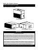
• B5SMairhandlersaresuppliedwithadirectexpansion
refrigerant coil and thermostatic expansion valves.
Refrigerant line connections are located on the motor
side (service side) of cabinet and require sweat
connections.
• TheB5SM-120airhandlerhasadualcircuitcoiland
the B5SM-090 has a single circuit coil.
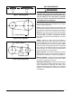
NITROGEN
HEALTH
FLAMMABILITY
REACTIVITY
0 Minimal Hazard
1 Slight Hazard
1
0
0
• TheB5SM-120airhandlerischargedthroughservice
valves on the end of the liquid tube for each circuit.
These must be removed before brazing the line sets.
The B5SM-090 is charged through a service valve
inside the unit, which should not be removed.
• Before brazing the B5SM-090, remove the core
from the service port. Failure to do this may result in
a leak at the service valve. Replace the core and cap
once brazing is complete.
• Optionalequipmentsuchasliquidlinesolenoidvalves,
low ambient, etc., should be installed in strict accordance
with the manufacturer’s installation instructions.
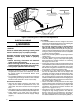
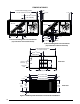
Filter Requirements
B5SM air handlers are shipped with three permanent
1” filters; however the filter rack can be converted to
accommodate a 2” filter as shown in Figure 1 (page 6).
To convert to a 2” filter:
1. Remove all filters from the unit.
2. Locate and remove the 4 screws (Figure 1, page 6)
holding the bottom filter slide assembly (latch end) to
the filter rack frame. NOTE: Be careful when removing
the slide assembly so it does not drop into unit and
cause damage to the coil.
3. Remove the 4 screws securing the “L” bracket to the
“Z” bracket.
4. Rotate the “L” bracket 180 degrees, and reposition it
soitmountsushwiththe“Z”bracket.SeeFigure1.
5. Secure the filter slide assembly together with the four
screws.
6. Re-install the filter slide assembly back into the filter rack
frame and secure with the 4 screws removed earlier. If
replacing factory supplied filters with disposable filters,
use only 2” disposable filters.
Accessing the filters does not require tools and can be
performedfromeithersideofthelter-rack.Ontheservice
side of the unit, locate the release knob at the base of
the filter rack and rotate clockwise to unlock, then pull up
andouttoremovethelteraccesspanel.Ontheblower
side, use the same method but rotate counter-clockwise
to unlock.