
Installation - Filter Cabinet User guide


Form I-CAUA-FC, Page 12
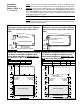
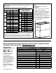
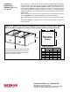
FIGURE 10 - Bottom Filter Cabinet with Bottom Duct Connection, Options CW13, CW14,
CW15, and CW16, supports the heater providing a ltered path for vertical return air.
Return air enters through the bottom of the lter
cabinet. See duct opening dimensions on right.
Cabinet may be placed with lter access doors
on either front or rear of heater.
www.ReznorHVAC.com; 1-800-695-1901
©2014 Reznor LLC, All rights reserved.
Trademark Note: Reznor
®
is registered in at least the United States.
05/14 (Serial No. Date Code BNE) I-CAUA-FC (Version .2)
Installation
Instructions -
Options CW 13, 14,
15, and 16
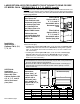
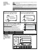
Option CW 13, 14, 15, and 16 return air lter cabinets are shipped factory assembled.
Position the lter cabinet in its nal location being careful to allow sufcient clearance
on the lter access side. After the lter cabinet is secure, set the Model CAUA on
the lter cabinet. (NOTE: Be sure hole has been cut in bottom of CAUA before placing
it on the lter cabinet; see Installation Preparation on page 11.) The lter cabinet is
designed so that there is no mechanical attachment required between the lter cabinet
and the heater.
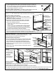
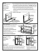
Attach return air duct to the duct ange on the bottom of the lter cabinet; see dimen-
sions in FIGURE 10. This completes installation of a bottom lter cabinet.
Sizes of eld-supplied or replacement lters are listed in the component table on page
11.
After heater installation is complete, turn on the electric and the gas and check for
proper operation.
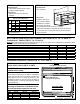
Size
A B
inches mm inches mm
150 25-1/2 648 32 813
200 25-1/2 648 32 813
250 37-1/2 953 32 813
300 37-1/2 953 32 813
350 37-1/2 953 46 1168
400 37-1/2 953 46 1168