
Installation - Filter Cabinet User guide

Form I-CAUA-FC, P/N166162R2, Page 5
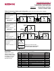
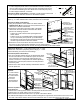
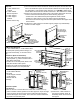
STEP 1 Parts Required:
2 Filter Supports (NOTE: Refer to the illustration and select carefully as
there is a lter support for the vertical (top) inlet conguration that will not
be used when assembling the lter cabinet with a horizontal (rear) inlet.);
2 Filter Support Channels; 12 Screws
Instructions (Refer to Illustration) - Assemble a lter support channel and
a lter support as illustrated. Total of two assemblies required.
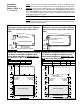
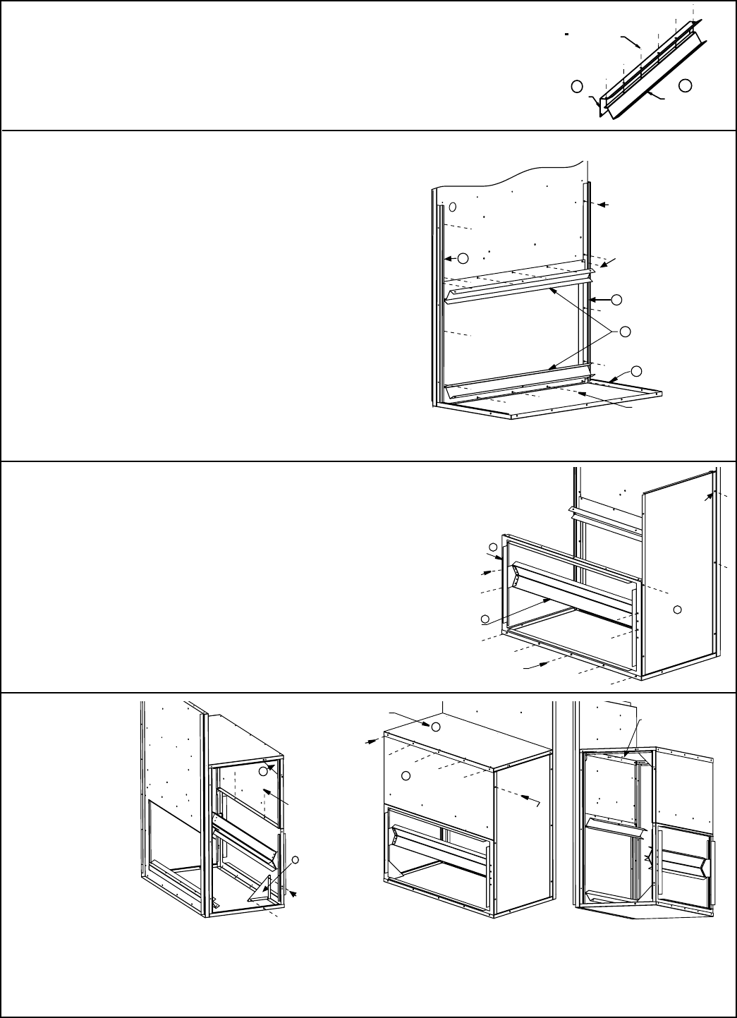
STEP 2 Parts Required: 2 Filter Cabinet Door (or Side) Channels; 2 Assembled Filter Support/Channels
(STEP 1); 1 Filter Cabinet Bottom Panel; 8 Screws from the Package
Instructions (Refer to Illustration):
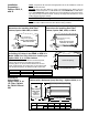
1) Using the "preparation" holes drilled in the heater cabinet
(FIGURE 2A or 2B) and screws from the kit, attach the two
cabinet door channels as illustrated.
2) Remove the screws along the bottom edge of the heater
cabinet and use those screws to attach the lter cabinet
pieces in the following sequence.
- Position the lter cabinet bottom panel against the
heater cabinet.
- Position one of the assembled lter support/channels
on top of the bottom panel (channel "up" as illustrated).
- Re-insert the screws securing both the bottom panel and
the lter support/channel to the heater cabinet.
3) Remove the row of screws above the cutout area. Position
the second lter support/channel assembly over the holes (channel
"down" as illustrated). Re-insert the screws, securing the assembly to the heater cabinet.
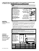
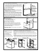
STEP 3 Parts Required: 1 Filter Cabinet Side Panel; 1 Filter
Cabinet Rear Inlet Panel (w/opening & duct ange); 1 Filter
Channel Assembly;12 Screws from the Package
Instructions (Refer to Illustration):
1) One end of the lter cabinet will have an attached side panel,
and the other will have a removable door panel. On the end
that is selected for the permanently attached panel, use
screws to secure the side panel to the channel (STEP 2).
2) Position the rear inlet panel; attach to the side panel and
the bottom panel.
3) Position the lter channel assembly as illustrated. Attach to
the rear panel inlet.
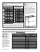
STEP 4 Parts
Required:
1 Filter Cabinet
Rear Top Panel
1 Filter Cabinet
Top Panel
2 Corner
Support Braces
16 or 18 Screws
Instructions (Refer to
the illustrations):
1) Position the rear top panel; attach to the side panel and the rear bottom inlet panel.
2) Position the top panel; attach to the rear top panel.
3) Reach inside the cabinet and attach the top panel to the heater cabinet.
4) To add structural support to the cabinet, position a triangular support brace in the bottom outer corner on the
door end of the cabinet. Fasten with two screws. Attach the other corner brace in the top outer corner.