
Installation - Filter Cabinet User guide


Form I-CAUA-FC, Page 8
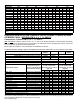
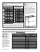
NOTES:
* Application requires 2" permanent lters; do not use pleated lters.
** If installing lter cabinet that attaches to the side of the heater (Option
CW 4, 5, or 6), two cabinets must be installed, one on each side.
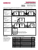
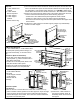
SMALL RETURN AIR FILTER CABINET FOR ATTACHING TO REAR OR SIDE
OF MODEL CAUA 150 OR 200 - OPTIONS CW 8, 9, 10
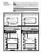
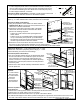
STEP 5 Vertical (Top) Inlet - Final
Steps
Parts Required: Door Assembly
Instructions:
Install the door on the end of the lter
cabinet. Fasten the latches.
Installation of the optional lter cabinet
with a vertical (top) inlet is complete.
Duct ange dimensions for connecting
ductwork are shown on page 6.
After heater installation is complete and
return air ductwork is connected, turn
on the electric and the gas and check
for proper operation.
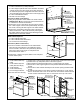
STEP 4 Horizontal Inlet - Install Filters
Parts Required: Filters (either shipped with the option package or
eld-supplied)
Instructions: Slide the lters into the lter rack channels.
Permanent or Pleated 2" Filters
for Options CW4, CW5, or CW6
Size CFM FPM Filters
150
1800 281 (4) 16 x 16
2400 375 (4) 16 x 16
3000 469 (4) 16 x 16
200
2400 375 (4) 16 x 16
3000 469 (4) 16 x 16
250
3000 469 (4) 16 x 16
*4000 625 (4) 16 x 16
**5000 781
(4) 16 x 16;
(4) 16 x 16
300
3000 469 (4) 16 x 16
*4000 625 (4) 16 x 16
**5000 781
(4) 16 x 16;
(4) 16 x 16
350
4300 448 (6) 16 x 16
5000 521 (6) 16 x 16
*6000 625 (6) 16 x 16
400
4300 448 (6) 16 x 16
5000 521 (6) 16 x 16
*6000 625 (6) 16 x 16
Permanent or Pleated 2"
Filters for Options CW7,
CW12, or CW11
Size CFM FPM Filters
150
1800 281 (4) 16 x 16
2400 375 (4) 16 x 16
3000 469 (4) 16 x 16
200
2400 375 (4) 16 x 16
3000 469 (4) 16 x 16
250
3000 313 (6) 16 x 16
4000 417 (6) 16 x 16
5000 521 (6) 16 x 16
300
3000 313 (6) 16 x 16
4000 417 (6) 16 x 16
5000 521 (6) 16 x 16
350
4300 448 (6) 16 x 16
5000 521 (6) 16 x 16
*6000 625 (6) 16 x 16
400
4300 448 (6) 16 x 16
5000 521 (6) 16 x 16
*6000 625 (6) 16 x 16
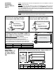
Components -
Options CW 8, 9, 10
Rear and side lter
cabinets, Options CW 8,
9, and 10, are shipped
separately for eld
assembly and installation.
(The cabinets are
assembled as they are
installed.) The table on the
right lists the Package P/N's
and the components in
each package by package
P/N and by Model Size.
Before beginning
installation, verify that all
parts are available at the
job site.
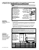
Filter Cabinet Components by Option Package - CW Options that attach to rear or side
For Model CAUA Sizes 150 and 200
Option CW8 (with 2" pleated lters) - Pkg P/N 166159
Option CW9 (with 2" permanent lters) - Pkg P/N 166160
Option CW10 (for eld-supplied 2" lters) - Pkg P/N 166161
Component Description
Filter cabinet attaches to side or rear of
heater with horizontal (rear) inlet only
Qty P/N
Bottom Panel 1 164537
Side Panel 1 164536
Rear or Top Inlet Panel (w/duct ange) 1 164533
Top Panel or Bottom Rear Panel 1 164537
Door Panel Assembly 1 166148
Door Channel 1 164535
Filter Support 2 164704
Filter Support Channel 2 164532
Filter Channel Assembly 1 166147
Sheetmetal Screws #10-32 x 1/2" long 20 113275
2" Permanent Filters * in Option CW9 4 114325
2" Pleated Filters * in Option CW8 2 114324
*See Step 5, page 11 for lter dimensions.