
Installation - Filter Cabinet User guide


Form I-CAUA-FC, P/N166162R2, Page 9
Installation
Preparation -
Options CW 8, 9,
and 10
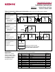
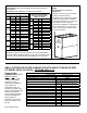
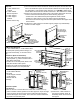
FIGURE 7 - Reference Drawing - inches (mm)
for Drilling 1/8" Holes in the REAR or SIDE of a
Model CAUA Size 150 or 200 when Installing an
Option CW 8, 9, or 10 Filter Cabinet
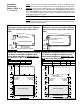
One end of the lter cabinet will have an attached panel,
and the other will have a removable door panel for
accessing lters. On the end that is selected for the door
panel, use dimension "F" to drill holes. On the end that will
have the attached panel, use dimension "G" to drill holes.
Sizes 150 & 200 F (use for "door" end) G (use for "attached panel" end
Side Panel 1-13/16 (46) 1-11/32 (34)
Rear Panel 2-15/32 (63) 2 (51)
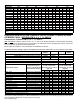
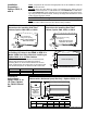
FIGURE 8 - Dimensions - inches (mm) - of a Return Air Filter
Cabinet with a Horizontal (rear) Inlet only - Options CW 8, 9, 10
Installation
Instructions -
Option CW 8, 9, or
10, Filter Cabinet
for CAUA 150 and
200
Sizes Option A B C D
150 and
200
CW 8, 9,
and 10
inches
34-11/16 32 21-5/32 12-1/2
mm
(881) (813) (537) (318)
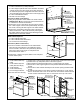
FIGURE 6B - Heater Inlet Air Opening
Dimensions for installing Rear Filter
Cabinet, Option CW8, CW9, or CW10
FIGURE 6A - Heater Inlet Air Opening
Dimensions for installing Side Filter
Cabinet, Option CW8 CW9, or CW10
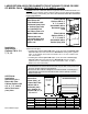
FIRST, verify that the kit received is the appropriate one for the installation. Check the
heater size and the CFM.
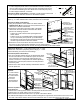
SECOND, where the lter cabinet is going to be attached to the heater, nd four
embosses in the metal panel. For rear attachment, see FIGURE 6B; for side attach-
ment, see FIGURE 6A. These embosses are corner indicators for the inlet air open-
ing. Using tin snips or aviation shears, carefully cut straight lines between the corner
marks until the opening is created.
CAUTION: The cut edges of the metal cabinet will be sharp.
THIRD, refer to the illustration in FIGURE 7. Drill the required 1/8" holes in the side or
rear of the heater cabinet where the lter cabinet is being installed.