EFMA Floor Heating System INSTALLATION GUIDE Oct. 2011 Edition By www.rezspec.
1.1 General Information . . . . . . . . . . . . . . . . . . . . . . . . . . . . . 5 Components . . . . . . . . . . . . . . . . . . . . . . . . . . . . . . . . . . 6 1.2 Always . . . . . . . . . . . . . . . . . . . . . . . . . . . . . . . . . . . . . 7 1.3 Never . . . . . . . . . . . . . . . . . . . . . . . . . . . . . . . . . . . . . . 8 2. Technical information . .
1. EFMA Floor Heating System 1.1 General Information IMPORTANT! The installation must meet the following building codes, as applicable: • Canadian Electrical Code (CSA C22.1) • American National Electricity Code (ANSI/NFPA 70) • Any other national or local code The EFMA floor heating system is composed of a heating cable fastened to an adhesive fiberglass mat along with a lead for connection to an electrical power source.
Components Two-phase conductor 120V: phase - neutral 240V/208V: phase - phase aramid fiber roving ground wire (bare wire) cold lead heating cable junction channel cold lead floor heating system heating cable wire insulation floor covering cement glue aramid fiber roving PVC sheath self-levelling cement heating wires ground wire aluminum sheath plywood or concrete slab Fig. 1.
1.
Do no t la ple t oor sensor t o floor sub Never stap le e fl th y items on EF eav yh able Ac M ting cable he a to e th he Never sta the heating cut c bfloor e su th er le ab Ne v • Install EFMA sections so that the heating cables are less than 76 mm (3”) from each other. The temperature could be too high and could cause damages; • Shorten or alter any part of the heating cable (Fig. 1.
2. Technical Information 8 2.1 Surface Area and Power Output of EFMA Products Product # 120V Width Length Surface area Power in. ft. sq. ft. Watts Resistance Ohm EFMA85AK1ELNG1 16 6’ 8 85 169.4 EFMA120AK1ELNG1 16 7’ 6” 10 120 120.0 EFMA150AK1ELNG1 16 10’ 13 150 96.0 EFMA170AK1ELNG1 16 11’ 6” 15 170 84.6 EFMA240AK1ELNG1 16 15’ 20 240 59.9 EFMA300AK1ELNG1 16 19’ 25 300 47.5 EFMA360AK1ELNG1 16 22’ 6” 30 360 39.6 EFMA420AK1ELNG1 16 26’ 6” 35 420 33.
Product # 240V/208V Width Length Surface area Power in. ft. sq. ft. Watts Resistance Ohm EFMA170AK3ELNG1 16 11’ 6” 15 170 338.8 EFMA240AK3ELNG1 16 15’ 20 240 240.0 EFMA300AK3ELNG1 16 19’ 25 300 192.0 EFMA360AK3ELNG1 16 22’ 6” 30 360 159.8 EFMA420AK3ELNG1 16 26’ 6” 35 420 137.0 EFMA475AK3ELNG1 16 30’ 40 475 121.1 EFMA600AK3ELNG1 16 37’ 6” 50 600 95.0 EFMA720AK3ELNG1 16 45’ 60 720 79.2 EFMA840AK3ELNG1 16 52’ 6” 70 840 67.
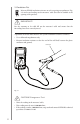
2.2 Insulation Test Measure EFMA’s insulation resistance at each step using a megohmeter (Fig. 2.2) and record readings on the measures’ table (this label is available at the opening of the product). IMPORTANT! For the warranty to be valid, fill out the measures’ table and ensure that the 10 readings have been correctly noted.
2.3 Resistance Test Measure the resistance of the EFMA heating cable at each step using a multimeter (Fig. 2.3) and record readings on the measures’ table. IMPORTANT! For the warranty to be valid, fill out the measures’ table and ensure that the 10 readings have been correctly noted. A qualified electrician must measure the system’s resistance as follows: • Use a calibrated multimeter only; • Measure resistance at the free end of the cold lead, between the two phase conductors; cold lead Fig. 2.
3. Types of Heating and Floor Covering 12 The EFMA floor heating system can be used for two purposes maximizing comfort. Used as a secondary heat source (floor warming), it can help keep floor temperature comfortable year round. Used as a primary room heat source (radiant floor heating), it provides uniform, comfortable, and enveloping warmth. For the latter use, it is important to follow the specific recommendations outlined below.
IMPORTANT! Do not install a radiant floor heating system on a noninsulated or poorly insulated subfloor, or over a crawl space. The efficiency of this type of primary room heating system will depend on factors such as surface area, heat conductivity of the floor covering, insulation on outside walls, etc. We recommend that you verify these points and seek professional advice before investing time and money. 3.
4. Installation Instructions 4.
10' temperature sensor Fig. 4.1 8' cold lead We can help optimize your work plan. Fax it to us at 724-662-3957. Clearly indicate all dimensions. A minimum of one horizontal and one vertical dimensions are necessary to validate the scale. 4.2 Preparing the Subfloor • Clean and remove any debris, dust or protruding objects that could damage the heating cable.
" Fig. 4.3 a • The floor temperature sensor must be centered between two parallel heating cables under the EFMA fiberglass mat (Fig. 4.3 b). The ideal location is one where it is likely to be away from stationary objects and sheltered from outside influences (sunlight) that could skew floor temperature readings. For maximum comfort, the area above the sensor must be free of obstruction. 10" 16" Fig. 4.
4.4 Installing the EFMA Floor Heating System Tape, spray adhesive, stapler Remove the product from the box and verify the electrical and insulation resistance of the heating cable. channel cold lead heating cable junction Fig. 4.4 a • Unroll the mat, adhesive side down (Fig. 4.
• Staple the mat to the plywood subfloor to prevent the mat ends from curling; • Use spray adhesive to fasten the EFMA to a concrete subfloor. Staple the mat to plywood Secure with an aerosol adhesive on concrete Fig. 4.4 b Fig. 4.4 c IMPORTANT! Never staple the heating cable directly to the subfloor. 4.4.
IMPORTANT! Never cut or try to shorten the heating cable. • • • • Ensure that the EFMA surface is flat against the subfloor; Avoid walking on the EFMA system.
4.5 Installing the Temperature Sensor Hot glue gun, hammer, wood chisel or concrete chisel channel temperature sensor Fig. 4.5 • To minimize floor height, chisel a 10 mm X 10 mm X 250 mm (3/8” X 3/8” X 10”) channel in the subfloor to receive the temperature sensor. CAUTION! The sensor must be embedded in cement or an equivalent binder (cement glue, ceramic glue, self-levelling cement). • Glue the sensor to the subfloor (Fig. 4.5).
4.6 Applying Self-Levelling Cement Fig. 4.6 Measure the cable’s electrical and insulation resistance and record the readings on line 3) Before embedding the heating cable in self-levelling cement of the measures’ table. • Consult the manufacturer’s instruction for the type of floor covering (ceramic, linoleum, or other). See Section 7, ”Expert Tips”; • Completely embed the heating cable in self-levelling cement (Fig. 4.6). It is crucial that the ENTIRE cable be embedded.
Final view floor covering self-levelling cement cement glue 4.7 Connecting the System IMPORTANT! The system must be connected by a master electrician. Cold lead - 240V/208V connection: Line 1–Black Line 2–Red Bare wire–ground - 120V connection: Line–Black Neutral–White Bare wire–ground Measure the cable’s electrical resistance and record the readings on line 5) Upon installing the thermostat of the measures’ table. 4.
• The EFMA floor heating system is now ready for use. However, before turning on the system, make sure the curing period specified by the cement or binder manufacturer has expired. Adjust the thermostat’s temperature based on your needs and desired level of comfort. 5. IMPORTANT! The EFMA system must be controlled by a temperature control system.
6. FAQ 6.1 Floor Heating System Q.1: A.1: Can I cut the EFMA heating cable to shorten it? NEVER. If the EFMA roll is too long, detach the excess cable from the mat and spread it on the floor in regular loops identical to those on the mat. Keep the minimum distance from the walls and between parallel runs of cable (radius bending of at least 20 mm [¾”] for loops). Q.2: A.2: What should I do before choosing the EFMA system that’s right for me? Sketch a plan to determine the surface area.
120V current will produce virtually no heat. It is therefore very important to connect the right product to the right voltage. Q.13: Can EFMA be installed over concrete? A.13: Yes. Apply a concrete sealer before installing the EFMA system. See Section 4. Q.14: Can carpet be installed over EFMA? A.14: Yes, if the system is completely embedded in self-levelling cement. You can install low-pile carpet over the slab if the carpet’s thermal resistance does not exceed R = 1.40 (RSI = 0.246). Q.
7. Expert Tips: Installation and Floor Covering 7.1 Installation Tips • For multilayer wood flooring (engineered floor) or linoleum, it is recommended that you consult the manufacturer to verify whether these floor coverings are compatible with a floor heating system; • Keep the strips of fiberglass mesh cut during installation and, as necessary, place them over the heating cable if you have detached it from the mat and laid it out by hand (Fig. 7.
Subject to the legal warranties relating to quality and durability of goods provided for by the Consumer Protection Act: REZNOR warrants the EFMA heating cables of its floor heating system for a 25-year period beginning from the date of purchase, against any malfunction or manufacturing defect.