
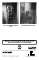
Installation - Elec Heating User guide

19
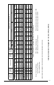
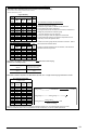
Excerpts from NEC 2005 handbook - based on NFPA 70
Partial Table 310.16 Allowable Ampacities of Insulated Conductors (0-2000 Volts)
- Not more then 3 current carrying conductors in cable or raceway
- Based on Ambient Temp of 30˚C
Copper Wire Only
Size Temperature Rating of Conductor Size
AWG
or
kcmil
60˚C 75˚C 90˚C
AWG
or
kcmil
14 20 20 25 14
How to Estimate Unit Supply Wire Requirements:
12 25 25 30 12
10 30 35 40 10 1) Determine Nominal Input Voltage
8 40 50 55 8 2) Estimate Length of Wire from Breaker to Unit Disconnect
6 55 65 75 6 3) Find Unit MCA for desired conguration
4 70 85 95 4
4) Using the minimum wire size based on the unit MCA, calculate the %
Voltage Drop to determine the initial wire gauge
3 85 100 110 3
2 95 115 130 2 The %VD should be 3% or less at the unit
1 110 130 150 1
5) Verify Unit Voltage is within the Appliances min/max limits
1/0 125 150 170 1/0
6) Verify that the Wire ampacity (corrected for temperature & the # of
conductors) is above the Appliances MCA
2/0 145 175 195 2/0
3/0 165 200 225 3/0
7) Based on nal wire gauge selection, determine conduit size. Refer to
NEC for details and allowable ll rate
Amb. Temperature Correction Factors
Amb.
Temp
(˚C)
Temperature Rating of Conductor
Amb.
Temp
(˚F)
60˚C 75˚C 90˚C
8) Based on Appliance MOP and nal wire selection, make selection of
Appliance branch circuit protection
21-25
1.08 1.05 1.04
70-77
26-30
1.00 1.00 1.00
78-86
31-35
0.91 0.94 0.96
87-95
36-40
0.82 0.88 0.91
96-104
41-45
0.71 0.82 0.87
105-113
46-50
0.58 0.75 0.82
114-122
51-55
0.41 0.67 0.76
123-131
Partial Table 310.15(B)(2)(a) Adjustment factors for more than three current-carrying
conductors in a raceway or cable
# of Current-Carrying Con-
ductors
Amount to adjust values in Table
310.16 after correction for Ambient
Temperature (if necessary)
4 to 6 80%
7 to 9 70%
Partial Table 9 Effective Impedance for 600V Cables, 3Ø, 60 Hz, 75˚C - 3 single current-carrying conductors in conduit
Uncoated Copper Wire Only
Effective Impedance (Z) at 0.85 PF
Ω to Neutral / 1000 ft
AWG
or
kcmil
PVC
Conduit
Aluminum
Conduit
Steel
Conduit
14 2.7 2.7 2.7
12 1.7 1.7 1.7
10 1.1 1.1 1.1
8 0.69 0.69 0.70
6 0.44 0.45 0.45
4 0.29 0.29 0.30
3 0.23 0.24 0.24
2 0.19 0.19 0.20
1 0.16 0.16 0.16
1/0 0.13 0.13 0.13
2/0 0.11 0.11 0.11
3/0 0.088 0.092 0.094
The above tables and recommended procedures are provided for reference only, for complete details refer to the current
version of the National Electric Code, the applicable local codes & ordinances, or consult a qualied professional.
100%
3
1000
9
×=
×=
××=
−−
−−−−
−−
tageNomLineVol
pVoltageDro
pVoltageDro
pVoltageDropVoltageDro
UnitMCA
ft
gthCircuitLen
ValueTablepVoltageDro
LinetoLine
NeutraultoLineLinetoLine
NeutraultoLine