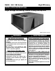
R6GN - 150 / 180 Series High Efficiency Installation Instructions Single Package Gas Heating / Electric Cooling Rooftop Units R6GN-150 Series Shown WARNING: FIRE OR EXPLOSION HAZARD • Failure to follow safety warnings exactly could result in serious injury or property damage. • Installation and service must be performed by a qualified installer, service agency or the gas supplier. • Do not store or use gasoline or other flammable vapors and liquids in the vicinity of this or any other appliance.
TABLE OF CONTENTS Important SAFETY INFORMATION........................3 REQUIREMENTS & CODES........................................4 GENERAL INFORMATION...........................................5 About the Rooftop Unit...............................................5 Before You Install This Equipment..............................5 Locating the Unit........................................................5 Heating Load..............................................................
important SAFETY INFORMATION Please read all instructions before servicing this equipment. Pay attention to all safety warnings and any other special notes highlighted in the manual. Safety markings are used frequently throughout this manual to designate a degree or level of seriousness and should not be ignored. WARNING indicates a potentially hazardous situation that if not avoided, could result in personal injury or death.
length of the supply and return ducts. Consideration should also be given to the accessibility of fuel, electric power, service access, noise, and shade. • The installer should become familiar with the units wiring diagram before making any electrical connections to the unit. See the unit wiring label or Figures 15 & 16 (pages 30 - 31). • Use caution when handling this appliance or removing components. Personal injury can occur from sharp metal edges present in all sheet metal constructed equipment.
GENERAL INFORMATION About the Rooftop Unit Single Package Gas Heating / Electric Cooling Rooftop Units are designed only for outdoor rooftop or ground level installations and can be readily connected to the duct system of a building. This unit has been tested for capacity and efficiency in accordance with AHRI Standards and will provide many years of safe and dependable comfort, providing it is properly installed and maintained.
Combustion Air & Venting Requirements WARNING: Carbon monoxide poisoning hazard Failure to follow the steps outlined below for each appliance connected to the venting system being placed into operation could result in carbon monoxide poisoning or death. The following steps shall be followed with each individual appliance connected to the venting system being placed in operation, while all other appliances connected to the venting system are not in operation: 1.
General Information WARNING: Installation methods other than those described in the following sections must comply with the National Fuel Gas Code and all applicable local codes for providing sufficient combustion air to the furnace. Provisions must be made during the installation of this unit that provide an adequate supply of air for combustion. • Instructions for determining the adequacy of an installation can be found in the current revision of the NFGC (ANSI Z223.1 / NFPA54).
• Make sure that the exhaust gases will not impinge on windows or building surfaces, which may be compromised or damaged by condensation. • Do not install the unit in a location where exhaust from the vent termination will be directed into windows, stairwells, under decks, or other recessed areas. Circulating Air Supply WARNING: Do not allow combustion products to enter the return air ductwork or the circulating air supply.
Unconditioned Spaces Wood Cap Assembly All duct work passing through unconditioned space must be properly insulated to minimize duct losses and prevent condensation. Use insulation with an outer vapor barrier. Refer to local codes for insulation material requirements. Top Crate Brackets Acoustical Duct Work Certain installations may require the use of acoustical lining inside the supply duct work.
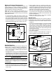
Minimum Clearance Requirements R6GN units are certified as combination heating and cooling equipment for outdoor installation only. Figure 5 displays the minimum clearances to combustible materials for both downflow and horizontal discharge.
Downflow to Horizontal Conversion The unit is shipped ready for downflow duct connections. If horizontal ducts are required, the unit must be converted according to the directions in the conversion kit for both the supply and return ducts. Condensate Drain The method for disposing of condensate varies according to local codes. Consult your local code or authority having jurisdiction.
IMPORTANT NOTES: • All gas piping must be installed in compliance with local codes and utility regulations. In the absence of local codes the gas line installation must comply with the latest edition of the National Fuel Gas Code ANSI Z223.1 or CAN/CGA B149 Installation Codes. • Some local codes require the installation of a manual main shut-off valve and ground joint union external to the furnace (Figure 9, page 13). The shutoff valve should be readily accessible for service and/or emergency use.
Piped Gas Supply Piped Gas Supply Drop Tubing Gas Supply Horizontal Drop Horizontal Gas Valve 3 in. Minimum Gas Valve Riser 3 in. Riser Min. Gas Valve 3 in. Minimum NOTES: 1. All piping must comply with local codes, ordinances, and/or National Fuel Gas Codes. 2. A manual shutoff valve must be installed within 6 feet of this equipment. 3. Always include a drip leg in piping. Figure 9.
ELECTRICAL WIRING WARNING: ELECTRICAL SHOCK, FIRE OR EXPLOSION HAZARD Failure to follow safety warnings exactly could result in serious injury or property damage. Improper servicing could result in dangerous operation, serious injury, death or property damage. • Before servicing, disconnect all electrical power to furnace. • When servicing controls, label all wires prior to disconnecting. Reconnect wires correctly. • Verify proper operation after servicing.
Unbalanced 3-Phase Supply Voltage Voltage unbalance occurs when the voltages of all phases of a 3-phase power supply are no longer equal. This unbalance reduces motor efficiency and performance. Some underlying causes of voltage unbalance may include: Lack of symmetry in transmission lines, large single-phase loads, and unbalanced or overloaded transformers. A motor should never be operated when a phase imbalance in supply is greater than 2%.
To change the blower speed: 1. Disconnect all electrical power to the unit. 2. Open the motor access panel. 3. Loosen the 4 motor mounting nuts. Turn the belt tensioning nut until belt can be removed from the sheave or pulley. 4. Loosen front set screw on the motor sheave. NOTE: Turning the set screw clockwise (close) increases the blower speed, or counterclockwise (open) decreases blower speed. 5. Replace belt on pulleys and position motor mounting plate to correct position for proper belt tension.
Air Circulation 1. Set the thermostat switch to OFF and the fan switch to ON. 2. Verify the blower motor runs continuously. Check for air delivery at the register(s). Ensure that there are no obstructions at the registers or in the ductwork. 3. Set thermostat fan switch to AUTO and verify the blower shuts down immediately. NOTE: If blower is turning opposite of arrow direction, shut off main power to the unit and switch any two field wires at the disconnect. DO NOT alter unit wiring. System Cooling 1.
blowers should continue to run when the over-temperature limit control switch opens. 3. Remove the close-off plate immediately after the overtemperature limit control opens. If the unit operates for more than four minutes with no return air, set the thermostat below room temperature, shut off power to the unit, and replace the over-temperature limit control. NOTE: On some low static/high airflow applications, the Over-Temperature limit control may not function.
OPERATING SEQUENCE The operating sequences for the heating, cooling, and fan modes are described below. Refer to the wiring diagrams (Figures 15 & 16, pages 30 & 31). Cooling Mode 1. On a call for cooling the thermostat closes, applying 24 VAC to Y1, G, & Y2 if Stage 2 cooling is calling. 2. G applies 24VAC to the main circulating blower circuit. 3. Y1 & Y2 apply 24VAC through all safety switches before energizing their respective contactors. 4.
Routine Maintenance Please consult your dealer for maintenance information and availability of maintenance contracts.At a minimum, routine maintenance should include the following items: WARNING: Never operate the unit without filters in place. Dust and lint in the return air can build up on internal components, resulting in loss of efficiency, equipment damage, and possible fire. • Inspect the condensate drain and outdoor coil at the beginning of each cooling season. Remove any debris.
12.Follow the operating instructions printed on the units gas valve label or Figure 17 (page 35) to return the unit to normal operation. Verify proper operation after servicing. 16.Follow the operating instructions printed on the units gas valve label or Figure 17 (page 35) to return the unit to normal operation. Verify proper operation after servicing. Cleaning the Heat Exchanger Removal of Unit Top Pan If the heat exchanger must be cleaned due to soot or scale build up, follow the steps below. 1.
COMPONENT FUNCTIONS The descriptions below are various functional components that affect the operation and shutting down of this unit. Some of these components and their locations are shown in Figure 11 (page 23). If any component on this unit must be replaced, use only Nordyne authorized replacement parts specified in the Replacement Parts List provided online. Flame Roll-Out Control - The flame roll-out control acts to verify that the burner flame is being drawn into the heat exchanger tubes.
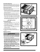
FIGURES & TABLES Condenser Coil Stage 1 High/Low Pressure Switch Protection Stage 1 Condenser Coil Stage 2 Liquid Line Filter Driers Aluminized Steel Tubular Heat Exchanger Evaporator Coil Condenser Fan Assemblies Easy Access Filter Panel Durable Pre-Coat Paint High Effciency Scroll Compressors with Crankcase Heaters (one opposite side) Heavy Gauge BaseRails For Lifting Electrical Disconnect Mounting Panel (Field Supplied) High/Low Pressure Switch Protection Burner Stage 2 Assembly Model R6GN-180C
physical Dimensions Dimensions shown in inches (mm) TOP VIEWS “B” CG CONDENSER FANS (2) CORNER “B” CONDENSER COILS VENT HOOD CORNER “D” “B” CG CONDENSER FANS (3) CORNER “B” CORNER “A” INDUCER/BURNER ASSY CONDENSER COILS R6GN-150 Series INDUCER/BURNER ASSY CORNER “A” 15.50 (394) 102 (2590) BLOWER MOTOR ACCESS COMPRESSOR ACCESS OPTIONAL HAIL GUARD HOOD † 43 (1092) 47 (1194) VENT HOOD CORNER “C” R6GN-180 Series 15.
ROOF CURB OUTLINE 3.5 (89) TYP 2" K.O. BOTTOM GAS SUPPLY ENTRY 15.31 (389) 10.31 (262) 5.31 (135) 4.5 (114) 8.5 (216) 20 (508) 16 (406) 68 (1727) 65.5 (1664) 79 (2007) 87 (2210) 41 (1041) SUPPLY AIR OPENING BOTTOM CONTROL WIRING ENTRY BOTTOM POWER WIRING ENTRY 2.5 (64) 16.5 (419) 2 (51) TYP RETURN AIR OPENING 2 (51) TYP 27 (686) 4.5 (114) 3.
0.4 0.5 0.6 0.7 0.8 0.9 1.00 1.10 5300 914 952 1.95 5000 5.0 Turns Open 990 1.84 4650 916 1.73 4300 1.87 4450 2.00 4600 2.13 4825 2.26 5050 917 936 954 973 991 1.62 3700 1.75 3900 1.87 4100 2.00 4400 2.13 4700 918 937 955 974 993 1.43 1.57 1.70 3550 1.84 3725 1.98 3900 956 976 995 1.54 1.70 1.85 3400 996 1.59 1.2 1.3 1.40 1.50 1.60 External Static Pressures (Inches Water Column) 1.
Table 5. R6GN-180C Series 27 0.4 0.5 0.6 0.7 0.8 0.9 1.00 1.10 6150 1085 3.07 5900 1085 2.95 5550 1086 2.82 5250 1087 2.68 4800 1088 2.51 6300 1066 3.10 6000 1067 2.88 5750 1067 2.76 5400 1068 2.64 5050 1069 2.50 4600 1070 2.30 6100 1048 2.92 5800 1049 2.75 5675 1049 2.61 5250 1050 2.49 4825 1051 2.36 6200 1028 2.84 5900 1029 2.73 5600 1030 2.61 5600 1030 2.45 5100 1031 2.33 4600 1032 2.21 3.5 Turns Open 4.0 Turns Open* 4.5 Turns Open 5.0 Turns Open 1.3 1.40 1.50 1.60 1.7 5100 1168 2.
Figure 13.
Figure 14.
R S R S R S Figure 15. Ladder Diagram - 150/180 Series Compressor 2 Compressor 1 T3 T2 T1 T2 CC1 95 SC-4 T1 T2 T3 L3 L2 L1 CC2 CC2 FUSE BLOCK OPTIONAL BOR 96 C1-2 C1-1 C2-2 C2-1 C1-2 C1-1 SC-4 CC1 SC-5 T1 C C C SC-5 IBC T3 Indoor Blower Motor Outdoor Fan Motor C1-3 Outdoor Fan Motor C2-3 Outdoor Fan Motor C1-3 IC-L1 IC-K4 IC-IND GND - Indicates plug connection. Letter Indicates which plug. Number indicates pin location.
Figure 16.
Table 6. Electrical Data 32 180,000 270,000 270,000 270,000 270,000 315,000 315,000 R6GN-150D-180C R6GN-150C-270C R6GN-150D-270C R6GN-180C-270C R6GN-180D-270C R6GN-180C-315C R6GN-180D-315C 268,000 268,000 230,000 230,000 230,000 230,000 153,000 153,000 LP 1.4 1.4 1.4 1.4 1.4 1.4 1.4 1.4 INDUCER MOTOR RLA 460/3/60 208-230/3/60 460/3/60 208-230/3/60 460/3/60 208-230/3/60 460/3/60 208-230/3/60 NOMINAL ELECTRICAL SUPPLY 414 187 414 187 414 187 414 187 Min.
GAS INFORMATION GAS FLOW RATES GAS FLOW RATES CUBIC FEET PER REVOLUTION OF GAS METER TIME FOR ONE REVOLUTION (SECONDS) 10 12 1 5 10 TIME FOR ONE REVOLUTION (SECONDS) 360 300 1,800 1,500 3,600 3,000 66 68 CUBIC FEET PER REVOLUTION OF GAS METER 1 5 10 55 53 273 265 545 529 14 257 1,286 2,571 70 51 257 514 16 225 1,125 2,250 72 50 250 500 18 200 1,000 2,000 74 49 243 486 20 180 900 1,800 76 47 237 474 22 164 818 1,636 78 46 231 462 24 150 750 1,500
NATURAL GAS UNIT MODEL NUMBER GAS TYPE HEATING INPUT (BTU/HR.) NUMBER OF BURNERS 0 to 2,000 FT 2,000 to 4,000 FT 4,000 to 6,000 FT 6,000 to 7,000 FT ELEVATION 661118 918839 918840 918841 Nordyne Part No. R6GN-150(C,D)-180C NAT. 180,000 4 1/8” 31 33 34 R6GN-150(C,D)-270C NAT. 270,000 6 1/8” 31 33 34 R6GN-180(C,D)-315C NAT. 315,000 7 1/8” 31 33 34 ORIFICE SIZE Table 9.
FOR YOUR SAFETY READ BEFORE OPERATING WARNING: If you do not follow these instructions exactly, a fire or explosion may result causing property damage, personal injury, or loss of life. POUR VOTRE SÉCURITÉ. À LIRE AVANT L’EMPLOI ATTENTION! L’inobservation de ces instructions peut entraîner un incendie ou une explosion pouvant causer des dammages à votre propriété à votre personne, ou la mort. A. This appliance does not have a pilot.
INSTALLATION / PERFORMANCE CHECK LIST GAS SYSTEM INSTALLATION ADDRESS: CITY_________________________ STATE_________________ Gas Type: (circle one) Gas pipe connections leak-tested? Natural Gas Propane YES NO UNIT MODEL #_________________________________________ Gas Line Pressure:_____________________________ (in - W.C.