Form No. RZ-NA I-RA/D 140/235 (Version A) Obsoletes Form I-RA/D 140/235 REZNOR® USED-OIL-FIRED HEATERS AND BOILERS Installation and Reference Guide Heater Models RA 140 RA 235 RAD 140 RAD 235 CSA Certified to Electrical and Fuel Burning requirements only.
IMPORTANT Notice to Owner and Installer To ensure the long term benefits of burning your used oil in a Reznor® Used-OilFired Heater, it is necessary to become familiar with the correct installation and maintenance of your new furnace. Before installing or operating this heater, make sure you have read and understand this manual. IMPROPER INSTALLATION OR LACK OF MAINTENANCE WILL VOID THE WARRANTY.
Table of Contents by Page No. INSTALLATION HEATER START-UP Introduction ..................................... 4 System Check ............................... 19 Priming and Leak Check ......... 19-20 Start-Up Procedure ................. 21-23 Use ............................................................. 4 Codes and Regulations .............................. 4 Warranty..................................................... 4 Safety Warnings ..........................
Installation Introduction Use This heater is for commercial or industrial use only. The heater should be installed by an experienced installer thoroughly trained and experienced with the installation of oil-fired appliances. The installer should be familiar with the special precautions necessary in the handling and storage of used automotive oils which may contain small amounts of gasoline.
Safety Warnings ! Conventions Used in this Manual Hazard Intensity Levels DANGER: Failure to comply will result in severe personal injury or death, and/or property damage. WARNING: Failure to comply can result in severe personal injury or death and/or property damage. CAUTION: Failure to comply could result in minor personal injury and or personal damage. NOTE: Additional Warnings are also included throughout this manual.
Safety Warnings Continued Air for Combustion WARNING: Care should be exercised to ensure that an adequate supply of combustion air is available and free to enter the air openings on all units. Room openings must equal one square inch per each 1,000 BTU heat input. Non-Compliance Failure to install or maintain this heater properly will void the warranty.
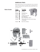
Additional Parts Shipped with each heater is a remote fuel pump and a carton of parts. The carton contains parts required for installation. Before beginning actual installation, verify that the remote fuel pump and the parts listed below are at the installation site. Parts Carton Part No.
Heater Placement Do not attempt to install this heater until you have read and understand this manual! Placement is critical to the efficient operation of this heater. Measure all distances to comply with the specific code requirements and minimum clearances listed below. Refer to the section on Venting your heater for vent requirements and recommendations. Locate the heater so that suitable means shall be provided to facilitate regular cleaning and maintenance of the heater (i.e.
High Altitude Installation High Altitude Installation Standard Model RA/RAD 140 and 235 used-oil-fired heaters are designed for use from sea level up to elevations of 3,000 ft. Without proper modifications severe overheating of the combustion chamber and heat exchanger will occur if installed above 3,000 ft. Also, the onboard air compressor will not deliver the correct amount of atomizing air to the fuel nozzle, resulting in poor combustion.
Fuel Tank, Pump, and Supply Lines Fuel Tank General Requirements Model RA/RAD 140 and RA/RAD 235 heaters are approved to burn used crankcase oil, transmission fluid, and No. 2 fuel oil. Maximum fuel input for a Model 140 is 1.0 GPH (4.5 L/H).Maximum fuel input for a Model 235 is 1.7 GPH (7.7 L/H). The oil supply tank and fuel lines must be installed in accordance with the National Board of Fire Underwriters requirements and all local ordinances.
Pump Remote Fuel Pump The Model OT-250 tank has a platform designed for attaching the remote fuel pump. • Attach the fuel pump legs permanently either on the platform, directly to a field-supplied tank, or in a location very near to the oil tank. • Mount the remote pump assembly in an upright, horizontal position as shown in the illustration. NOTE: Do not mount the pump assembly in a vertical or inverted position. CAUTION: Do not use TEFLON® based pipe dope or TEFLON® tape to seal any pipe connections.
Supply Lines Installation Continued Suction Line (cont’d) Return Line Discharge Line (portion of supply line from pump to heater) Supply Line Connections and Support as illustrated. With the vacuum gauge mounted on the outlet side of the filter, the gauge will indicate any suction line restriction including a dirty filter. A pump inlet manifold is supplied for direct connection of the filter to the inlet of the pump.
Mounting the Heater General Requirements Before suspending the unit, check the supporting structure to ensure it has sufficient load-carrying capacity to support the weight of the heater. Model Net Weight lbs kg RA140 290 132 RA235 343 156 RAD140 352 160 RAD235 410 186 Use four 1/2”-13 diameter threaded rods. Lock each threaded rod using a washer and nut as shown in the illustration below. Or, use optional swivel connections (Option CK10) and field-provided 1” threaded pipe.
Venting the Heater WARNING: Failure to provide proper venting could result in death, serious injury, and/or property damage. Units must be installed with a flue connection and proper vent to the outside of the building. Safe operation of any gravity vented heating equipment requires a properly operating vent system, correct provision for combustion air, and regular maintenance and inspection.
• Any portion of the vent system that passes through an unheated space or a concealed area such as an “attic” must be a factory-built vent that is approved to Standard UL 641. See illustration . . . . . . . . . . . • The heater may be vented into a masonry chimney that complies with the BOCA National Mechanical Code for low-heat appliances or other building code requirements for lowheat appliances.
Detailed Requirements for the Vent System (read all before beginning installation) (cont’d) • Barometric Draft Regulator: A barometric draft regulator which is the same diameter as the vent pipe must be used, and it should be located close to the heater. See page 16. Do not install a manual damper or any other device that will obstruct the free flow of the flue gases.
Installing Ducts Inlet Air Duct Inlet Air Duct Discharge Duct Discharge Duct Model RAD CFM (free air) Air throw (9 ft suspension) CFM .25" ESP 140 2000 50 ft 15M 1425 Canadian installations require field installation of an inlet air duct (return air system) on a Model RAD heater. The blower-equipped heater has an inlet air duct flange.
Heater Power Installation DANGER: Make sure that the main circuit is OFF before making any wiring connections.
Heater Start-Up Burner Start-Up System Check Check Test - Prior to Start-Up You should check your system completely before operating it. Check clearances from combustibles. Be certain that the clearances are in compliance with the appropriate Codes. Check hangers and supports. Be certain that all hangers, supports, and arms are adequately anchored and that all unions or threaded fittings are snug and do not rotate. Heater must be level. Check to make sure all shipping supports have been removed.
Priming and Leak Check Continued For control locations, refer to illustration on page 38 2. Set manual disconnect switch to the ON position. 3. Fill the suction line (line between the supply tank and the pump) with clean used oil. (Do not use new motor oil.) 4. Locate the rubber tubing connecting the pressure switch in the main control box and the compressor. • Disconnect the tubing at the fitting on the compressor. This will prevent oil from flowing to the burner. 5.
Heater Start-Up Start-Up Procedure Check-Test Check Test - After Start-up After installing and testing your unit, follow the procedure below to start the system. • Turn on the main electrical supply to the heater. • Set the manual disconnect switch to the “ON” position. • Set the thermostat to a temperature above room temperature. NOTE: When the low oil temperature limit senses the proper oil temperature, the green light on the burner junction box will come on and the heater will fire.
Check-Test Continued WARNING: If there is insufficient draft, it will create a back pressure resulting in oil fumes in the building and/ or pulsating when the burner starts and stops. It may cause excess deposits of soot and overheat the heat exchanger resulting in premature failure of the chamber. THIS TYPE OF FAILURE IS NOT COVERED UNDER THE WARRANTY. To correct this problem, the height of the chimney may need increased and/ or a UL or CSA/ULC listed draft inducer may be installed.
Check-Test Continued Check Discharge Air Temperature - Model RAD with discharge ductwork only. This heater is designed for a maximum of .25” w.c. static pressure and for discharge air temperature rises from 40° to 50°F. If the heater has been equipped with a duct, the discharge air temperature should be checked.
Maintenance General Maintenance Requirements Maintenance Schedule WARNING: Turn off electric power to the unit before doing any service or maintenance on the heater. When burning used automotive diesel and truck oils, this heater will require more frequent service than conventional heating equipment. All used oils contain a small amount of ash. This ash is similar in texture to that found in wood burning fireplaces, and varies with the types of oil used.
Every Six months: • • • • • • Clean the oil strainer at the burner. Clean the foot valve screen. Replace the air filter. Clean the end cone. Replace the oil nozzle. Clean the external surfaces of the combustion chamber/heat exchanger. • Clean the fan or blower. • Check for oil leaks. • Check blower belt for tension and wear. • Inspect the electrodes • Clean the pre-heater. NOTE: A maintenance record chart is provided in the Appendix.
Cleaning the Pump Cont’d pump cover. Go to the instructions for “Recharging the Suction Line” (below). Pump Screen Gasket 2. Remove and Clean the Screen • To access the screen, the pump cover must be removed. • Remove the four bolts that hold the pump cover. (Be careful, pump is full of oil). • Remove the cover being careful not to lose or damage the gasket. • Remove the circular screen and clean with a solvent and compressed air.
Maintenance Continued Cleaning Combustion Chamber, Heat Exchanger and Flue Pipe WARNING: Used oils may contain engine-wear metal compounds and foreign materials. When burned, these compounds are deposited within or exhausted from this heater. Therefore, care should be taken when using, cleaning and maintaining this equipment. Whenever any cleaning including the flue pipe and exhaust stack is done, proper protective equipment, including gloves and a face mask or respirator, must be worn.
Maintenance Continued Inspecting and Cleaning the Heat Exchanger/Combustion Chamber View with Inner Access Door Removed If tubes are 25% blocked, leave covers off and proceed with cleaning. (cont’d) Combustion Chamber Heat Exchanger Tubes Removing Soot and Ash from the Combustion Chamber, Heat Exchanger, and Flue Pipe 1. On the burner end of the heater, remove the access panel underneath the service tray. • Pull the door panel straight out from the heater. 2.
Maintenance Procedures Continued Replacing the Compressed Air Filter Locate the compressed air filter. • Remove the wing nut, the cover plate, and the filter. • Properly discard the old filter and replace with a new filter (Reznor P/N 107216, Wix Filter No. 43274, or NAPA No. 2374). • Fasten with cover and wing nut. Compressed Air Filter Removing Burner and Cleaning End Cone, Nozzle, and Electrodes WARNING: Turn off the electric power before burner is removed for service.
• Clean nozzle by disassembling, washing thoroughly, and blowing dry with compressed air. • If nozzle face appears worn, replace the oil nozzle with P/N 102997. Annual nozzle replacement is recommended. This nozzle is custom designed. Do not substitute nozzle. • Replace the end cone. NOTE: Be sure NOT to damage the “O” ring on the nozzle. If the “O” ring appears damaged, replace the nozzle. 4.
Maintenance Procedures Continued 6. The fuel line assembly may now be removed by either • Pulling the assembly up slightly and toward the rear of the burner housing. • OR removing the burner and end cone and pulling straight out of the blast tube. See pages 29-30 for details. Fuel Connection Transformer in the “open” position Fuel Line Assembly Removed Servicing/Replacing Spark Electrodes To service or replace the Spark Electrodes Remove any carbon formation on the spark electrodes.
Maintenance Procedures Continued Reassembling the Fuel Line Assembly 1. To reassemble the Fuel Line Assembly • Slide the fuel line assembly into the burner housing and the burner tube. 2. Connect the fuel connection assembly to the fuel line assembly. • Tighten the 5/16” inverted flare nut firmly. Then tighten the connection nut. Do not move the escutcheon plate. • Check the spacing between the oil nozzle and the end cone. Refer to Electrode Adjustment” #4 (page 31). 3.
Maintenance Procedures Continued Cleaning Oil Pre-Heater System Continued 3. Clean the Pre-heater • Place the pre-heater in a vice and carefully remove the outer cylinder and the “O” ring. NOTE: There will be oil in the pre-heater. • Clean the inner section with a cloth and degreaser such as carburetor cleaner. Be careful not to “clean” the electrical controls. Do not immerse in cleaning fluid. • Clean the outer portion of the cylinder with degreaser. Inner Cylinder Outer Cylinder 4.
Service Notes General Service General Operation Reznor® used-oil-fired heaters have been designed and manufactured to provide years of trouble free operation. However, as with any type of mechanical equipment, it can malfunction. For your safety, we suggest that if you are unfamiliar with servicing this type of equipment, contact a qualified service person.
General Operation Continued CAUTION: Do not reset the primary control more than one time. If the heater does not ignite, contact your service person. assure that the correct atomizing air pressure is available, a pressure switch permits oil flow to the nozzle only when a minimum of 9 psi is sensed. Combustion air is supplied by a blower contained in the burner housing. An adjustable air shutter and air band located on the outside of the burner housing control the quantity of combustion air.
Troubleshooting Oil Burner Troubleshooting To diagnose malfunctions properly, the following test equipment is required: 1) An electrical test meter that can measure AC volts, ohms, and amps; 2) A combustion analyzer kit to measure oxygen and/or carbon dioxide, smoke, stack temperature, and draft; and 3) Two pressure gauges with scales of 0-100 PSIG and 0-30 PSIG.
Backflow Sensor Switch Continued Location - The backflow sensor switch is mounted on a bracket on the hinged viewport cover on the control side of the heater. The location is important in the operation of this switch. Except for limited observation, the viewport cover must be kept closed for the sensor (and heater) to operate properly. Operation - Underneath the sensor bracket, the viewport cover has a 3/8” diameter hole.
Troubleshooting Continued Location of Components Referenced in Troubleshooting Charts Backflow Sensor Switch on the Viewport Door (not illustrated) - on heaters installed in Canada beginning 1/96; on all units beginning 1/02 10 amp fuse mounted on the end of the electric box. See wiring diagram. NOTE: Fuse is on all units installed in Canada; on U.S. units beginning 1/02. Ignition Controller Green Light: Limits are satisfied; heater is ready to operate.
Chart No. 1 - Thermostat calling for heat; Burner motor never attempts to run. Troubleshooting Continued Turn on or correct supply. Wait 15 minutes for heater to warm up. Check for line voltage at the manual disconnect switch. Is voltage read? NO NO Refer to illustrations on page 38 and 40. Has there been line voltage across Terminals 1 and 2 for at least 15 minutes? YES YES Replace manual disconnect (on/off) switch.
Oil Heat Exchanger and Fuel Line Assembly Reference Chart No. 1 Troubleshooting Continued Locations and Replacement Instructions for Heating Element and Temperature Controls on Oil Pre-heat Heat Exchanger Refer to illustration on page 38. Low Oil Temperature Limit (black leads) Oil Temperature Control (blue leads) High Oil Temperature Limit Switch (yellow leads) Remove limit switches with open-end wrench. Do not rotate using terminals.
Troubleshooting Continued Refer to illustration on page 38. Chart No. 2 - Thermostat calling for heat, burner motor never attempts to run (green light is lit) indicating “System Ready”. Chart No. 1 has been successfully completed. NOTE: After ignition control is reset, you will have 30 SECONDS to perform the tests shown below before the controller locks out. Reset ignition control: Press the RED BUTTON, hold for four seconds, and release. DO NOT RESET MORE THAN ONE TIME.
Troubleshooting Continued Chart No. 3 - Thermostat is calling for heat. Burner motor runs for about 30-45 seconds. System does not attempt to ignite. First, check combustion chamber for excess oil. NOTE: After ignition control is reset, you will have 30 SECONDS to perform the tests shown below before the controller locks out. Reset ignition control: Press the RED BUTTON, Transformer and Electrode Checks: hold for three seconds, and release.
Chart No. 4 - Burner ignites and burns steadily until the system goes into lockout. Troubleshooting Continued 1. Remove cad cell wires from the ignition controller. 2. Start the burner. 3. Jumper F-F terminals on the ignition controller. Does ignition controller lockout? YES Replace ignition controller. NO Measure resistance across cell leads (F-F terminals on the ignition controller). Is resistance zero? YES Correct short circuit. Adjust for proper CO2.
Troubleshooting Continued Chart No. 5 - Thermostat calling for heat. Burner operation erratic/unstable flame pattern. Refer to illustration on page 38. Bleed oil from burner tee bleeder for ten minutes. Is stream of oil perfectly solid and continuous with no sign of air? NO YES Are the heat exchanger tubes restricted with ash? Run vacuum test on suction line to check for air leaks. Did suction line pass vacuum test? NO Repair suction line leak.
Chart No. 6 - High Temperature Limit Cycles* Troubleshooting Continued Does the fan/blower operate? Refer to illustration on page 46. Check for line voltage across fan/blower leads. Is voltage read? NO YES YES Replace fan/blower motor. YES Replace air discharge limit (fan/limit assembly). NO Check for line voltage across Terminals 1 and 2. Is voltage read? NO Check wiring.
Troubleshooting Continued Fan and Limit Controls Model RA/RAD 140 and 235 heaters are equipped with a fan control and limit control assembly consisting of a specially designed control mounting bracket with a fan control, a circulating air high limit control, and a super high limit control attached. To access the fan and limit control assembly, remove the plate as illustrated. For service information, see Troubleshooting Chart 6, page 45.
Troubleshooting Continued Is there sufficient oil in the supply tank? Chart No. 7 - Oil Delivery System CAUTION: If the heater will be shut down for a long period, turn off the electric power. NO Fill oil tank. Replace or repair. YES NO Is the pump turning? NO Check pump and motor drive components and set screws. Are they OK? YES YES Replace fuel pump motor.
Appendix 15 14 13 12 11 1O 9 8 7 6 5 4 3 2 1 1 1 1 18 Y BK BK WIRING CODE BLACK - BK BROWN - BR RED - R ORANGE - O YELLOW - Y GREEN - G BLUE - BL PURPLE - PR WHITE - W H Y #14 GA. BK G 15 OIL HEATER LOW TEMP LIMIT BK BK R Y H FAN CONTROL #12 GA.
Form I-RA/D 140/235 (Version A), Mfg No.
Hour Meter/Cleaning Record Cleaning Date Meter Reading Form I-RA/D 140/235 (Version A), Page 50 Initials Cleaning Date Meter Reading Initials
Index Air Band and Air Shutter Settings ....................... 22 Backflow Sensor Switch ...................................... 36 Belt Tension ........................................................... 6 Burner .................................................................. 29 Cleaning Record .................................................. 50 Clearances from Combustibles .............................. 8 Codes and Regulations .......................................... 4 Combustion Chamber ..........
FOR SERVICE OR REPAIR, FOLLOW THESE STEPS IN ORDER: FIRST: Contact the Installer Name ___________________________________ Address ___________________________________ ___________________________________ ___________________________________ Phone ___________________________________ SECOND: Contact the nearest distributor (See Yellow Pages). If no listing, contact Authorized Factory Representative, 1-800-695-1901 (Press 2).