
Installation - Power Venting Owner's manual


Form I-UD-V-PV, Page 8
3.7 Vent Terminal (cont’d)
Commercial/Industrial Installation
Models UDAP and UDBP - ALL Sizes
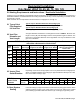
FIGURE 3 - Horizontal Vent Terminal - Commercial/Industrial Installation
(NOTE: Read all measurements; drawing is not proportional.)
TABLE 6 - Horizontal Vent
Terminal Clearances
A Reznor
®
Option CC1 vent cap is
required. Maintain a clearance of 6 to
12 inches (152-305mm) from the wall
to the vent terminal cap for stability
under wind conditions.
Products of combustion can cause
discoloration of some building
nishes and deterioration of masonry
materials. Applying a clear silicone
sealant that is normally used to
protect concrete driveways can protect
masonry materials. If discoloration is
an esthetic problem, relocate the vent
or install a vertical vent.
Structure
Minimum Clearances for Vent
Termination Location (all
directions unless specied)
Forced air inlet within 10 ft (3.1M) 3 ft (0.9M) above
Combustion air inlet of another
appliance
6 ft (1.8M)
Door, window, or gravity air inlet
(any building opening)
4 ft (1.2M) horizontally
4 ft (1.2M) below
1 ft (305mm) above
Electric meter, gas meter*, gas
regulator*,
U.S. - 4 ft (1.2M) horizontally
Gas regulator * U.S. - 3 ft (0.9M)
Adjoining building or parapet 6 ft (1.8M)
Adjacent public walkways 7 ft (2.1M) above
Grade (ground level) 1 ft (305mm) above**
*Do not terminate the vent directly above a gas meter or service
regulator.
** Consider local snow depth conditions. The vent must be at least 6”
(152mm) higher than anticipated snow depth.
3. Venting Requirements and Instructions - Commercial/Industrial Installation
- applies to ALL Sizes of Models UDAP and UDBP (cont’d)