® 0803UDSA-2GBEN UDSA 008-2 / 100-2 Gas fired Balanced flue / Fan assisted flue unit heater INSTALLATION COMMISSIONING SERVICING These appliances meet the following EC Directives: DIR CE 90/396/EEG:GAD DIR CE 89/336/EEG:EMC DIR 73/23/EEG:LVD DIR 89/392/EEG:MD WARNING Please read this document carefully before commencing installation, commissioning and/or servicing. Leave it with the user or attached to the appliance or gas service meter after installation.
INDEX Warnings ......................................................................................................................... 3 1. General...................................................................................................................... 4 2. Installation codes ...................................................................................................... 4 3. Warranty .......................................................................................................
Warnings FOR YOUR SAFETY What to do if you smell gas: • Do not try to light any appliance. • Do not touch any electrical switch; do not use any phone in your building. • Immediately call your gas supplier. • Evacuate all personnel. FOR YOUR SAFETY Do not store or use petrol or other flammable vapours and liquids in the vicinity of this or any other appliance. WARNING: Improper installation, adjustment, alteration, service, or maintenance can cause property damage, injury, or death.
1. General Models UDSA 008-2 through 100-2 are design certified to the CE EN1020 standard for use in industrial and commercial installations only. All models and sizes are available for use with either natural, propane or butane gas. The type of gas, the input rate and the electrical supply requirement is shown on the heater rating plate. Check the rating plate to determine if the heater is appropriate for the intended installation. This installation manual is shipped with the heater.
. Dimensions & Clearances (horizontal orientation=standard) Figure 1 Top view Rear view (all mod. except 035-2,0432,050-2) Front view Rear view ( only mod. 035-2,043-2,050-2) Side view Legend: 1. Combustion air inlet 2. Flue connection 3. External gas connection 4. Electrical connections 5.
Clearances (mm) Units must be installed so that the minimum clearances in the following table are provided for combustion air space, inspection and service and for proper spacing from combustible materials. Table 2 : Clearances (mm) Model X Y Z (*) U V 008-2 Æ 030-2 450 50 50 50 850 035-2 Æ 100-2 450 100 100 100 850 (*) : Heaters can be base mounted on suitable non combustible supports.
6. Technical data Table 4 : Technical data TYP E S 008-2 Æ 030-2 Type 008-2 011-2 015-2 C omb. A ir & Flue, type B instal. 020-2 025-2 030-2 II2H3+ B22 Gas category 1 1 C 12, C 32, C 42, C52, C 62,C 82 C omb. A ir & Flue, type C instal..
7. Flue requirements Model UDSA-2 heaters may be installed as Type-B and Type-C installations. Flue must be in accordance with BS6230 or BS5440. Local requirements may apply in addition to national requirements. These unit heaters are designed to operate safely and efficiently with either a horizontal or vertical flue system when installed with the specific requirements and instructions.
Flue outlet Venter outlet attachment requirements: Depending on the size of flue pipe as determined in table 5, attach either the flue pipe directly to the collar or a taper-type connector. WARNING : Single wall flue pipe exposed to cold air or run through unheated areas should be insulated to avoid condensation. Provision must be made for the condensation to flow freely to a point to which it can be released, i.e. a drain or gully.
Figure 3 : Type B appliances : Combustion air and flue pipe sockets all mod., except. 035-2,043-2, 050-2 only mod. 035-2, 043-2 & 050-2 1) Flue pipe outlet collar 2) Combustion air inlet opening Air supply WARNING : When these air heaters are installed in type B applications, designed to take air for combustion from the space in which it is installed. Do not restrict the combustion air intake.
Combustion air inlet pipe & flue pipe for balanced flue installation (type C appliances) Balanced flue air heaters are designed to be fitted with a combustion air inlet duct that obtains outdoor air and a flue pipe that exhausts flue products to outdoors. Both the flue and combustion air pipes must be sealed. Type C2 appliances must not be applied ! Figure 4 : Approved appliances type C C12 C32 / C62 C12b/C62 C52 Figure 5 : Type C appliances : Combustion air and flue pipe sockets all mod. except.
8. Location heater Remark: Flue requirements may affect location. Consult section 7 before making a final determination. Use the minimum clearances in section 5 and the throw data in the technical data table of section 6 when determining where to suspend the heater. Recommended minimum height is 2.5mm. WARNING: If touched, the vent pipe and internal heater surfaces that are accessible from outside the heater will cause burns. Suspend the heater such that these components cannot be touched.
9. Hanging the heater WARNING: Check the supporting structure to verify that it has sufficient loadcarrying capacity to support the unit weight. Suspend the heater only from the threaded nut retainers or with a manufacturer provided kit. DO NOT suspend from the heater cabinet panels. . Before suspending the heater, check the supporting structure to verify that it has sufficient load-carrying capacity to support the weight of the unit. Leave the unit on the pallet.
Figure 7 : Wall bracket kits (optional) When desired the heaters may be supported by wall brackets. Supporting in this manner allows the heaters to be placed in close proximity to the ceiling or mounted directly to the vertical supporting structures of the building. There are 2 different wall bracket designs for UDSA-2 models as shown in the illustrations below.
10. Gas Piping and pressures WARNING: All components of a gas supply system must be leak tested prior to placing equipment in service. NEVER TEST FOR LEAKS WITH AN OPEN FLAME. Failure to comply could result in personal injury, property damage or death. Warning : This appliance is equipped for a maximum gas supply pressure of 50 mbar. WARNING : Pressure testing supply piping Test pressures above 50mbar : Disconnect the heater and manual valve from the gas supply line which is to be tested.
11. Electrical supply and connections DANGER : THIS APPLIANCE MUST BE EARTHED. The electrical installation may only be carried out by an appropriately qualified person current to IEE Regulations. The supply line to the heater should include a main switch. The minimum clearance distance between the contacts must be more than 3 mm. All electrical connections should be made in the heater control compartment (refer to figure 9). Screw type terminals are provided.
Figure 9 : Wiring connections on the terminal board 0803UDSA-2GBEN, Pag.
12. Check installation & start-up Check the installation prior to start-up Check suspension. Unit must be secure.Verify that no other parts are fitted which are not individually supported and secured. Check clearances from combustibles. Requirements are in section 5. Check vent system to be sure that it is installed according to the instructions in section 7, venting requirements. Check piping for leaks and proper gas line pressure. Bleed gas lines of trapped air.
Operating instructions and operating sequence 1. Set thermostat to the lowest setting. 2. Turn off all electric power to the heater. 3. Shut the gas cock at the inlet of the unit. 4. Wait five (5) minutes to clear out any gas. Then smell for gas, including near the floor. If you smell gas, STOP! and follow the steps in the WARNINGS printed on page 3. If you do not smell gas, proceed to the next step. 5. 6. Turn on the electric power to the heater. Open the gas cock at the inlet of the unit. 7.
Burner gas pressure adjustment The gas pressure is set for the required heat input before the appliance leaves the factory. Provided that the gas supply to the air heater is in accordance with the supply pressure described on the appliance data plate, the operating pressure will not require adjustment.
Figure 10b : HONEYWELL gas valve (type 035-2 -> 100-2) 6 8 7 5 1 3 2 4 Legend 1) Gas inlet 2) Gas outlet 3) Inlet pressure tap 4) Outlet pressure tap 5) 6.3mm AMP terminals and screws for wiring 6) 6.3mm AMP terminals 7) Earth terminal/screw (line voltage models only) 8) Pressure regulator adjustment screw Table 8 : Burner jets and pressures 008-2 011-2 015-2 020-2 025-2 030-2 035-2 043-2 050-2 055-2 064-2 073-2 085-2 100-2 Nat. Gas (G20) Prop.
Ignition system Normal Heat Cycle Operating Sequence This heater is equipped with a direct spark integrated control relay. The control relay monitors the safety devices and controls the operation of the venter motor and the gas valve between heat cycles. The time line below illustrates a normal heat cycle. Power to gas valve and ignitor Start pre-purge Sensor checks for the presence of a flame Energisation of venter motor.
13. Maintenance & Service Warning : If you turn off the power supply, always turn off the gas. The material contained in the MAINTENANCE AND SERVICE Section of this manual is designed to aid a qualified service technician in maintaining and servicing this equipment. This heater will operate with a minimum of maintenance.
Figure 11b - Control panel assy located on a removable bracket 15 17 18 Legend: 15) Control relay (ER) 16) Terminal blocks 17) 2 stage burner relay K1.2 (option) (not illustrated) 18) Relay (K1.6) 19) Connector 20) Filter 21) Pressure switch (S3) 22) Electronic burner relay fuse 21 22 19 14. Heat exchanger Maintenance 16 20 This heater is equipped with a patented T-CORE2® heat exchanger. Remove any external dirt or dust accumulation. Visually check the heat exchanger for cracks and holes.
15. Burner Maintenance Burner removal 2 This heater has a unique one-piece T-CORE ® burner assembly designed to provide controlled flame stability without lifting or flashback. The burner can be removed as a unit for inspection or service : see below for removal instructions. Inspect the burner/control compartment annually to determine if cleaning is necessary. If there is an accumulation of dirt, dust, and/or lint, clean the compartment and follow the instructions below to remove and clean the burner.
6. Remove burner a) Locate the burner body front support. Remove the screws that attach it to the secondary air shield. Refer to fig. 14 for component definitions. Figure 13a b) Holding the venturi tube, slide the entire burner slightly to the right to disengage the burner from the supports on the left. Then rotate the open end of the venturi tube outward away from the heater. Carefully pull the burner assembly out of the cabinet. Figure 13b Figure 14 - Burner removal steps 2.
Inspect and clean the burner With the burner assembly removed, shine a flashlight on the burner ribbons. Look for carbon buildup, scale, dust, lint, and/or anything that might restrict flow through the spaces between the burner ribbons. Holding the burner assembly so that any foreign material will fall away from the burner, use a stiff bristle brush to loosen Figure 15 and remove any foreign material(s). If the burner is excessively dirty, remove one of the burner end caps.
Figure 16a Ignitor showing required spark gap measurement Figure 16b Flame sensor Caution : Due to high voltage on the spark wire and electrode, do not touch when energized. Flame sensor - Refer to figure 11a and locate the flame sensor. Disconnect the wire, remove the screw and the flame sensor. Clean with an emery cloth.. Control relay - See figure 17. The electronic burner relay monitors the operation of the heater including ignition. Do not open the control relay.
Figure 18 - Fan blade position on the motor shaft 3. Remove the fan assembly (fan guard, motor and fan blade). 4. Disassemble and replace parts as needed, then reassemble. Be sure the fan blade is in the proper position on the shaft; refer to the illustration and table in figure 18. Table 9 : Dimensions A S ize 008 011 015 020 mm 29 23 50 49 Fan ventilatormotor motor Fan blade ventilatorwiel 20.
Venter wheel position on shaft UDSA models 008-2 - 020-2 (Rotation clockwise from motor shaft end) Figure 19 Venter motor plate Motor mounting bracket Venter wheel Motor cooling fan 8 mm 8 UDSA models 025-2 - 030-2 (Rotation clockwise from motor shaft end) Figure 20 Venter wheel Venter motor plate Motor mounting bracket Motor cooling fan 8 mm 0803UDSA-2GBEN, Pag.
UDSA models 035-2 - 100-2 (Rotation counter clockwise from motor shaft end) Figure 21 Venter motor plate Motor mounting bracket Venter wheel Motor cooling fan 8mm 8 mm 21. Operating gas valve WARNING: The operating valve is the prime safety shutoff. All gas supply lines must be free of dirt or scale before connecting to the unit to ensure correct sealing. The main operating quick opening gas valve is powered through the thermostat and safety controls.
22. Combustion air pressure switch DANGER : Safe operation of this unit requires proper venting flow. Never bypass the combustion air pressure swtich or attempt to operate the unit without the venter operating. 23. Limit controls If a limit control needs replacing, use only the factory authorized replacement part for the size of heater. For approximate limit locations, see figure 11a.. The combustion air pressure switch ensures that proper combustion airflow is available.
24. Flue and combustion air piping Check the complete system at least once a year. Inspection should include all joints, seams, concentric adapters and the flue terminal cap. Replace any defective or heavily corroded parts. 25. Troubleshooting The integrated control relay monitors the operation of the heater. If the heater fails to operate properly, review the flow chart below and see the operating sequence in section 16.
Trial for ignition Call for heat Is there a spark across gap at igniter? YES Does gas ignite? YES Is there m in. flame current at the flam e sensor? YES NO Is there m in.
General Troubleshooting P ROBLEM Venter motor will not start P ROBABLE CAUS E 1. No power to unit. 2. No power to venter motor. 3. Integrated burner relay defective. 4. Defective venter motor. 5. Fluse blown (F3.1). 6. Fuse burner relay blown. 7. LC1 open. REM EDY 1. Turn on power, check supply fuses or circuit breaker. 2. Check connections at burner relay and/or venter motor terminals. 3. Replace burner relay. 4. Replace venter motor. See Section 26. 5. Replace fuse. 6. Replace fuse. 7.
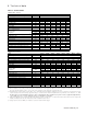
26. Parts list Description Control relay Spark ignitor Flame sensor Limit control LC3 Limit control LC1 Fan control KFC Pressure switch Pressure switch Pressure switch Relay Burner-on indication lamp Reset switch Mains filter Gas valve nat. gas 1st Gas valve nat. gas 1st Gas valve nat. gas 2st Gas valve prop. 1st Gas valve prop. 1st Gas valve prop.